
Свойства Wire
Created: сентября 26, 2019 | Updated: октября 16, 2019
| Applies to versions: 20.0, 20.1 and 20.2
Вы просматриваете версию 20.0. Для самой новой информации, перейдите на страницу Свойства Wire для версии 21
Parent page: Wire
Schematic Editor object properties are definable options that specify the visual style, content and behavior of the placed object. The property settings for each type of object are defined in two different ways:
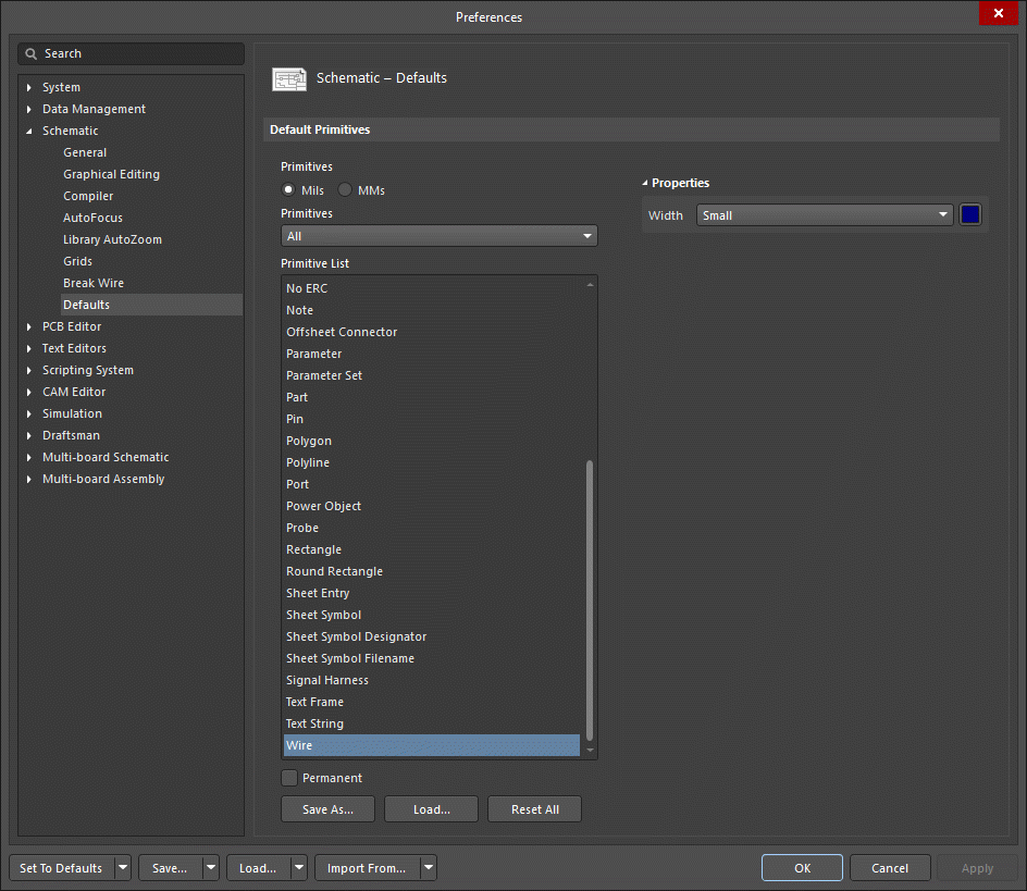
- Pre-placement settings – most Wire object properties, or those that can logically be pre-defined, are available as editable default settings on the Schematic - Defaults page of the Preferences dialog (accessed from the
 button at the top-right of the workspace). Select the object in the Primitive List to reveal its options on the right.
- Post-placement settings – all Wire object properties are available for editing in the Wire dialog and the Properties panel when a placed Wire is selected in the workspace.
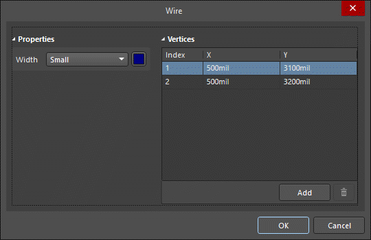
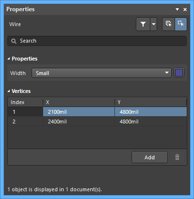
Properties
- Width - use the drop-down to select the desired width. Choices are: Smallest, Small, Medium, and Large. Click the color box to select the desired color for the object.
Vertices (Properties panel only)
- Vertices Grid - lists all of the vertex points currently defined for the object in terms of:
- Index - the assigned index of the vertex (non-editable).
- X - the X (horizontal) coordinate for the vertex. Click to edit.
- Y - the Y (vertical) coordinate for the vertex. Click to edit.
- Add - click to add a new vertex point. The new vertex will be added below the currently focused vertex entry and will initially have the same X,Y coordinates as the focused entry. Click the
 to remove the currently selected vertex.