
KB: Xpedition Migration Fails to Link Footprints and Import PCB Rules
 Altium Designer
Solution Details
Important Context
The guide explains the complete migration sequence, including schematic import, PCB import, library import, PCB rule translation, and post-import validation activities.
Converted Components Lose PCB Associations
After importing an Xpedition design into Altium Designer, PCB footprints may not be linked to their corresponding schematic symbols. When an ECO is generated, Altium Designer may attempt to remove components from the PCB because the component relationships cannot be resolved. In some cases, PCB constraints and design rules defined in the original Expedition design are also missing from the converted PCB.
Import Settings Prevent Automatic Mapping
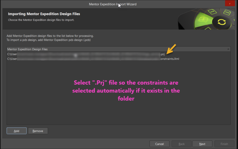
In Expedition, the footprint reference is stored in the Cell Name field. If the Altium import process uses a different field for footprint linking, schematic symbols cannot automatically associate with PCB footprints. Additionally, PCB constraints and rules are not imported when converting only the standalone .PCB file. Constraint information is retained only when the Expedition .prj project file is used during PCB import.
Use Correct Import Workflow and Settings
- Set the footprint link field to match Expedition's Cell Name value during schematic import.
- Import the PCB using the Expedition
.prjproject file to retain constraints and design rules. - Review the generated import log file for warnings, unsupported objects, and conversion issues.
- Move the converted PCB into the same project as the converted schematics and perform schematic-to-PCB synchronization.
- Validate imported PCB rules and design constraints after synchronization.
- Use Footprint Manager as a fallback when automatic footprint linking fails for specific components.
Preserve Footprints and Constraints During Migration
Migration Sequence Overview
- Import schematics using Mentor xDxDesigner Designs and Libraries.
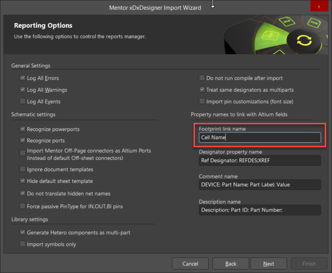
- Set Footprint Link Name = Cell Name.
- Import PCB using Mentor Expedition Designs and Libraries.
- Select the Expedition
.prjfile.
- Select the Expedition
- Move the converted PCB into the schematic project.
- Link schematic and PCB components.
- Synchronize using an ECO.
- Validate imported rules and constraints.
Schematic Import and Footprint Linking
- Start the Mentor xDxDesigner Designs and Libraries Import Wizard used for schematic migration.
- Proceed through the wizard until the reporting and mapping options page is displayed.
- Set Footprint Link Name to Cell Name.
- Complete the import process.
PCB Import and Constraint Conversion
- Start the Mentor Expedition Designs and Libraries Import Wizard.
- Select the Expedition
.prjfile instead of the standalone.PCBfile. - Complete the PCB import process.
- Review the generated import
.logfile and investigate any warnings or conversion issues reported during import. - Move the converted PCB document into the same project as the schematic documents.
- From the PCB document, select Project » Component Links » Perform Update.
- Select Design » Update PCB Document to generate and apply the ECO.
- Verify that schematic symbols and PCB footprints are correctly linked.
- Validate imported design rules and constraints.
Manual Footprint Assignment
- Create a library from the design documents.
- Open Footprint Manager.
- Assign the correct footprint to each affected schematic component.
- Update the schematic and run the ECO again.
Additional Notes
- Footprint assignment through Footprint Manager requires library-based components. Create a library from the design documents before attempting manual footprint reassignment.
- After migration, run project validation, ERC checks, and PCB rule verification to identify issues that may not be immediately visible after component linking is restored.
- The migration guide includes an extensive post-import verification checklist covering electrical, physical, rule, power, documentation, and reporting validation activities.
- Consider comparing generated manufacturing outputs with the original Expedition design as part of the final migration validation process.