Clone and Modify an Arduino Mega PCB Schematic in Altium Designer

Table of Contents
There are many different Arduino boards available for development and prototyping, and you might consider designing your own Arduino PCB schematic. If you want to modify an Arduino Mega schematic, you need design software that lets you easily build around an Arduino board and quickly add functionality. Your design software should make it easy to use any Arduino mega pinout board, like the Arduino Uno PCB schematic, Mega, Zero, or another model. The best PCB design software with comprehensive layout and management features is the best option for modifying an Arduino Mega schematic.
ALTIUM DESIGNER
A heavily rules-driven PCB design platform for designing industry-standard PCBs and Arduino PCB schematics.
Arduino boards are a great platform for getting started with a new device. If you’re a hobbyist or you’re just getting started building a functional prototype, the Arduino Mega pinout is a great platform to help you get started. These boards include plenty of I/O pins, an MHz speed oscillator, dedicated power, and USB connectivity. If you’re still learning the finer points of schematic design and PCB layout, you can use Arduino design files to help you get started building your own Arduino variant.
A bare Arduino Mega board is great for prototyping, but creating your own variant takes the right set of schematic design and PCB layout tools. Once you are ready to create an Arduino Mega clone or an original board, try working in Altium Designer’s unified environment. You can instantly import an Arduino Mega schematic and component libraries, and you can start modifying them with a set of integrated design tools.
Getting Started with an Arduino Mega Schematic
Development boards like Arduino, Raspberry Pi, and BeagleBone are great for breaking into electronics design. If you have a great idea for a new device, but you don’t have the time to learn the finer points of PCB design, you can create a prototype and develop code with the Arduino platform. You’ll have a pre-built board that has a small footprint, plenty of digital and analog inputs, USB connectivity, a built-in EEPROM, and MHz clock speed.
These boards are also a good option for startups looking to build decent functional prototypes. Eventually, you will need to move on to beta testing a real device, especially if you intend to create a mass-produced device. Once you’re ready to modify an Arduino schematic, you’ll need design software that can take the existing design files and import them into your PCB design tools.
Tools for Modifying an Arduino PCB Schematic in Your PCB Design Software
Although Arduino boards are a quick and easy way to start building a new device, you’ll still be limited by the hardware on these boards. If you want to modify existing Arduino Mega schematics to create a new board, your PCB design software needs the following features:
- A schematic editor that takes components from design libraries
- PCB layout and routing features for modifying Arduino schematic software and circuit board layouts
- Bill of materials tool that automatically compiles components from design libraries
- Assembly and fabrication drawing features
- Simulation features that help you evaluate your new design before production
When you have access to PCB design software with the best design features, you can easily modify an Arduino schematic or layout and create your own printed circuit board. You’ll be able to expand on the built-in Arduino mega pinout components while keeping everything in a single, compact package.
- Using an Arduino board on its own or in concert with your custom PCB is a great way to start developing a new IoT device.
Learn more about using Arduino schematics to build new IoT devices.
- Using an Arduino board is a great way to start prototyping your new product and experimenting with new features. You’ll want to complement the existing features with new functions and components.
Learn more about the core elements in an Arduino-based system.
- Newer Arduino models are production-grade, meaning you can develop your embedded code on an Arduino prototype and deploy it on a professional Arduino platform.

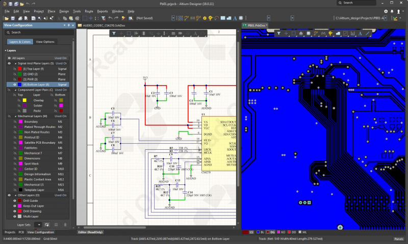
The schematic editor and PCB layout features in Altium Designer let you modify an Arduino Mega schematic and layout.
How to Update an Arduino Schematic
PCB design begins with an electronics schematic that shows how all your pins and components link together to form a complete, functional device. This document is more than just a drawing of pins and circuits; your PCB design software needs extensive component libraries in order to include all of your component information in your schematic. You can take advantage of the built-in microcontroller, digital and analog I/O’s, and onboard memory on an Arduino schematic to get your new idea off the ground.
Arduino schematics may not be available in Altium Designer’s file format, but the import and conversion tools still allow you to import schematics and begin creating your own board. Once you import the schematics, you can start editing the schematic sheets to add new components and functions. Utilizing Arduino can help you quickly get started creating a new board around a proven platform.
Add to Your Arduino PCB Schematic a Huge Component Library
Altium Designer includes extensive component libraries with the standard parts used in Arduino controllers and will allow you to get started modifying schematics quickly. You can then import other parts into your schematics to create new functions for your device. Once you’ve completed your schematic, simply use the integrated schematic capture tool to create a blank circuit board layout, and you can start wiring up components on your cloned Arduino board.
- If you’re adding new functions to an Arduino Mega Schematic, you’ll need to use a schematic editor that supports hierarchical schematics.
- Once you’ve modified your Arduino Mega schematic sheets, you need to capture your board as a blank circuit board layout.
Learn more about using schematic capture to create a PCB layout in Altium Designer.
- Arduino boards are great for driving small stepper motors, screens, LED arrays, and sensors for different applications.
Learn more about working with stepper motors in your circuit board.

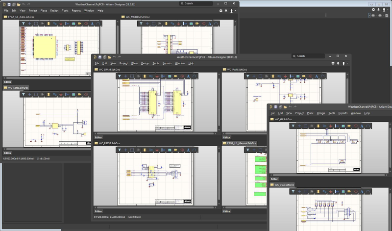
You can easily modify multiple schematics in Altium Designer.
Altium Designer’s Unified Circuit Board Design Environment
If you’re ready to clone an Arduino board or design circuits around an Arduino, you need adaptable design software. Altium Designer gives you access to a massive component library and the best design tools, making it easy to add new parts and functions to an Arduino schematic or design your own Arduino variant. The rules-driven design engine in Altium Designer makes sure all your design tools communicate with each other.
Best of all, the online DRC engine checks your PCB layout as it's created, helping you catch design errors before you send your new design off for prototyping and production. The CAD layout features, schematic editor, component search tools, and multi-board layout tools make it easy to build your next device on top of an Arduino board. You can take advantage of the existing capabilities in Arduino PCB schematic software (e.g., ICSP header, also known as an Arduino sketch and hardware (e.g., Arduino Mega and integrate these functions into your own designs.
Working in a Unified Environment
Most PCB design software programs don’t create a unified environment. Only Altium Designer places all your printed circuit board design tools into a single interface. Between a massive component library, powerful schematic editor, PCB layout features, and manufacturing planning tools, you have everything you need to create a custom Arduino board.
- When you use the unified set of design tools in Altium Designer, you can easily modify existing schematics and PCB layouts, including Arduino Mega schematic and layout files.
Learn more about the unified design environment in Altium Designer.
- Altium Designer is the only PCB design platform that includes a full set of PCB design features. You can take a new product from idea to full scale production with a single program.
Learn more about the full set of design features in Altium Designer.
- If you’re making a new product from an Arduino schematic, you can use the native 3D MCAD features to create an enclosure for your new product.

The unified design interface in Altium Designer lets you easily modify an Arduino Mega schematic and create a new layout in a single application.
If you’re starting out with an Arduino board and you plan to build around it, you’ll need a PCB design platform that gives you all the features shown above, and many more. The rules-driven design environment in Altium Designer helps you follow all the right PCB design and manufacturing guidelines when modifying your Arduino PCB schematic. Whether you’re designing a single PCB prototype or a complex multi-board system, Altium Designer has the tools you need to get through PCB fabrication and assembly.
Altium Designer on Altium 365 delivers an unprecedented amount of integration to the electronics industry until now relegated to the world of software development, allowing designers to work from home and reach unprecedented levels of efficiency.
We have only scratched the surface of what is possible to do with Altium Designer on Altium 365. You can check the product page for a more in-depth feature description or one of the On-Demand Webinars for more information on Arduino Mega PCB layout.


