Designing Capacitive Touch Sensor PCBs in Altium Designer

If you’re familiar with the way smartphones and other devices with touch screens work, then you’re already familiar with capacitive touch sensors. These sensors do more than just allow touch screens to distinguish fingers from other objects. Many sensors use capacitive sensing, sensors for measuring proximity, displacement, force, humidity, and fluid level. With the number of HMI devices that are projected to come into demand in the near future, engineers need tools to design and simulate these sensors directly on PCBs. Altium Designer contains all the features you need for capacitive touch sensor PCB design and much more.
ALTIUM DESIGNER®
The only PCB design package with a comprehensive toolset for capacitive touch PCB design sensors and much more.
The age of IoT is here, and new devices are coming online for interfacing with the environment and with humans. These devices require sensor arrays to gather data, as well as processing capabilities to process, store and transmit this data to the cloud. One type of sensor with broad functionality is capacitive sensors, which convert a change in capacitance and the resulting current due to charging or discharging to a digital signal.
When it comes to capacitive touch PCB design, your PCB design and layout play a critical role in determining the sensor performance of the device. The right layout for your sensor can maximize the responsivity of the sensor and lower parasitic capacitance, which helps maximize the signal-to-noise ratio with these devices. With the right design tools, you can easily integrate capacitive touch sensors into your next PCB.
PCB Design Process for Capacitive Touch Sensors
Designing a capacitive touch sensor on your Printed Circuit Board requires determining whether you will take advantage of changes in self-capacitance or mutual capacitance in the sensing element. The touch sensor can be easily controlled with an MCU. A self capacitive sensor only requires one input (Rx) pin to be used to sense the signal from the touch sensor, while a mutual capacitive sensor uses a Tx and Rx pin in order to receive the signal from the sensor.
Unless you are using a commercially available capacitive touch sensor, you will need to print the conductors for your sensor directly on your board. You will then need to couple your conductors to a continuous ground plane that runs beneath each conductor. With a mutual capacitive touch sensor, you will need to send a stream of bits from the Tx pin to one conductor, and the other conductor is left floating while connected to the Rx pin. With a self capacitive touch sensor, you only need to worry about connecting the Rx pin to your conductor.
Printing Touch Sensor Elements with Your CAD Tools
The right CAD tools in your PCB design software will allow you to complete two important tasks in capacitive touch sensor design. First, you can accurately size and layout the conductors you need for your sensor. Second, you can access a 3D model for the dielectric cover for your touch sensor and place it directly on your sensor.
- The right CAD tools make it easy to design sleek conductive elements directly on your PCB and connect these elements to the required supporting electronics. Learn more about designing conductors for your capacitive touch sensor.
- The Atmel QTouch integrated circuit offers an integrated solution for capacitive sensors in PCBs.
- Electromagnetic compatibility is one important aspect of capacitive touch sensing design that some designers overlook. Learn more about designing your PCB to ensure EMC in Altium Designer.

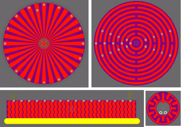
These are just a few examples of the conductor arrays you can create with the CAD tools in Altium Designer
Capacitive Touch Sensor Applications
A capacitive touch sensor can be used for a number of applications. In addition to sensor direct contact between a human finger and a dielectric, a capacitive touch sensor can be configured to sense proximity without making direct contact with the sensor. These sensors can also be designed to measure the precise position of a finger on a sensor. With some additional calculations in the MCU, this same array can be configured to detect motion across the sensor. If avoiding interference from water is an important consideration, you’ll be better off using a mutual capacitive touch sensor.
Designing for Capacitive Touch Sensing Applications
Just like a sensor that measures direct static contact with a human finger, PCB design software for capacitive touch sensors needs accurate CAD tools that do not limit your conductor layout to a specific geometry. With the right component libraries, you can easily add models for your supporting electronics to your Printed Circuit Board and design a complete capacitive touch sensing solution.
- With the right design software, you’ll have access to all the tools you need to include capacitive touch sensors for any application.
- Your component libraries should contain the parts you need to support and control a capacitive touch sensor. Your design software should also make it easy to add new components to your library and immediately start working with them in your design.
- As more IoT devices come online, these devices will likely include capacitive touch sensors alongside an array of other sensors for interacting with the environment.

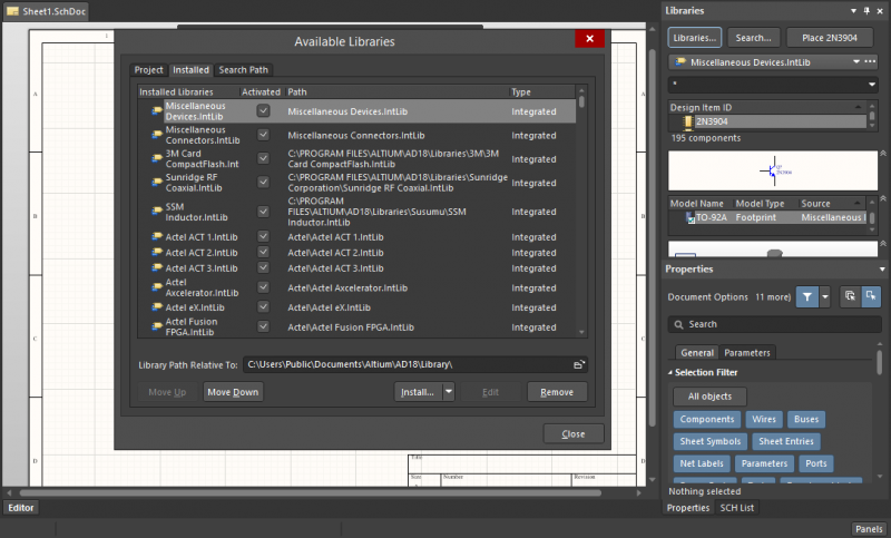
Accessing components in unified component libraries
PCB Design Software for Capacitive Touch Sensors
Touch sensors are deceptively simple elements, but designing them takes the right CAD and layout tools. Your CAD tools need to allow you to define copper pours in any geometry you can imagine, and you’ll need a layer stack manager in order to place your ground and power planes at the right locations in your layer stack. With Altium Designer, you’ll have access to all of these design features and much more in a single design environment.
Use Altium Designer for Your Next Capacitive Touch Sensor PCB
Altium Designer contains the important tools you need for capacitive touch sensor PCB design, as well as many other tools that help you integrate these sensors with other components. This design software includes a complete design hierarchy that standardizes your design data and helps you move to production seamlessly and all within a single design environment. No other design software offers this level of integration.
- Altium Designer places all your important design tools into a single program with a consistent interface. See Altium Designer’s unified design environment in action.
- The native 3D design tools give you a complete view of your entire device, allowing you to accurately place your capacitive touch sensor on your PCB. Learn more about Altium Designer’s native 3D design tools.
- When you are ready to produce your board, you’ll need to generate complete documentation for your manufacturer. Learn more about generating manufacturer deliverables in Altium Designer.
Other design platforms lack the functionality you need to design custom capacitive touch sensors directly on a PCB. Instead, you’ll be limited to the functionality offered by commercially available sensors, and other programs may not include models for these components. Instead, you need to work with the only integrated design software that includes support for a massive number of components and integrates all your important design tools into a single program.
When you choose Altium Designer, you’ll always have access to the resources you need to design successfully. From the AltiumLive forum to podcasts and a massive knowledge base, you’ll have plenty of resources to help you reach design success. It’s time to make the switch to the best PCB design platform on the market. It’s time to try Altium Designer.


