Troubleshooting Your Next PCB Design: Printed Circuit Boards Problems with Circuit Simulation and Analysis

Table of Contents
Troubleshooting a PCB usually occurs after it has been received from a production run, or after it has been used for some time. Using design rules, error checking, and simulation tools during the design process can help you avoid receiving defective boards from a production run. You’ll also be able to diagnose and troubleshoot signal integrity problems that can arise from overlooking important design standards. Only the latest and greatest unified PCB design software can help you do all of this simultaneously, and all within a single interface.
ALTIUM DESIGNER
A heavily rules-driven, fully unified Printed Circuit Board design suite.
PCBs continue to become more complex as time goes on, requiring more advanced design techniques. With so many design rules that need to be followed, your PCB software should have tools that can help you verify the proper functionality of your device. This is where design rules and simulation tools become critical. Your design rules help ensure that you can meet basic design standards and your particular technical requirements, while simulation tools can help you diagnose potential problems before moving to production.
Design rules can be either standardized or customized. Standardized design rules help ensure that your design will meet basic requirements for a broad range of applications. Customized design rules can be useful for ensuring your Printed Circuit Board will meet design requirements for very specific applications. Great design software will allow you to prioritize your design rules and can access these rules throughout your design software.
Using Design Rules to Ensure Proper Functionality
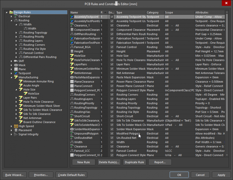
Your design rules are critical to ensuring your PCB can function as designed and that it meets basic design standards for your application. Unless you have a photographic memory, you probably don’t have an entire list of design rules memorized. This means that great PCB design software should include plenty of standardized design rules and give you the ability to create new design rules that are specific to your application.
Defining design rules is very important in Printed Circuit Board design, but no one can keep track of all the important and relevant design rules while they are drawing up a schematic or laying out components. This is where your PCB design software has to make up the difference. Your design software needs to interactively check your schematic and layout against your design rules and present warnings or errors in an intuitive interface.
How Rules-Driven Design Prevents Design Problems
As you design your next device, your design software should make it easy to check your design against standardized rules. Any rule violations should be presented in a simple interface and highlighted directly in your schematic and layout. This makes it easy to locate and troubleshoot any PCB design issues that can cause problems in your device before you start working with simulations.
- Different electronics applications demand different design rules to ensure proper functionality. Your PCB design software should be adaptable to any application. Learn more about customizing your design with flexible design rules.
- Design rules in your PCB design software are about more than placing components. Your design rules are critical in PCBs that include embedded software. See how your design rules can help you manage embedded software in your PCB.
- Working with design rules is about more than just rules checking. You can actually improve your workflow when you work in a rules-driven design environment. Learn how to improve your workflow with design rule checking.

Editing design rules and constraints in Altium Designer
Troubleshooting PCBs Before Production
Even if you followed standard design rules and tried to account for any other potential problems with custom design rules, there are times where your PCB assembly may still have signal integrity or power distribution problems. Design rules are designed to prevent these problems rather than diagnose them. It is important to check for any problems prior to production, lest your manufacturer deliver you a batch of unusable boards.
Power in your PCB must be distributed across all your electronic components, and a slight amount of power can be lost as it is sent to downstream components. A great PCB design software package with a power delivery analysis tool can be used to locate this problem and give you an idea of how components should be rearranged in order to compensate for any power losses.
Signal integrity problems can also arise and can cripple a PCB designed for high speed, high frequency, or low power applications. These signal integrity problems can be diagnosed using simulation and analysis tools. Once you locate a problem in a simulation output, you’ll need to take one or more steps to correct it. Doing this during the design phase allows you to try several methods to eliminate signal integrity problems.
Simulation and Analysis Tools in PCB Design
No one can rely solely on design rules alone when designing PCBs. In the same way, no one can rely solely on simulation tools to ensure a PCB meets basic design standards. Your PCB design software should provide all of these tools in a single environment, giving you the power to confront any design challenge and diagnose signal and power problems during the design phase.
- Power delivery analysis is critical to ensuring that all the components on your PCB will function properly.
Learn more about the symptoms of a bad power delivery network.
- Working with signal integrity simulations aids the high-speed design process and troubleshooting. See how you can incorporate signal integrity simulations in the design and troubleshooting process.
- Checking for errors against your design rules ensures that your PCB will actually work as designed. You can also troubleshoot errors before you move to production. Learn more about error checking with design rules.

Power delivery analysis in Altium Designer
Simulation and Design Rule Checking in a Unified Platform
Working with design rules and simulation tools is very useful for preventing and addressing a number of design problems in your PCB. Your design rule-checking features should be there to guide you through the design process, reporting any problems to you along the way. These should always be addressed during design as this will help you get your schematic and layout just write.
Once you get your design just so, simulations can be used to diagnose other potential problems that cannot be quickly addressed using design rules. Simulations allow you to address more complicated problems like signal reflection in unterminated traces and power delivery problems due to IR drop. Both of these toolsets need to work together, and the best way to do this is to use a unified design interface.
Altium Designer: Unifying Design, Analysis, and Production
The design engine in Altium Designer is heavily rules-driven. Rules checking and compliance form the core of the design process, yet you still have the ability to adapt the software to your particular application with custom design rules. Altium Designer also includes the most comprehensive simulation and analysis tools. All of these features give you the power to diagnose potential problems with your board during the design phase.
- Altium Designer was built with rule-driven design at the forefront. Your PCB design can be checked against standard and custom design rules. Learn more about rules-driven design in Altium Designer.
- Altium Designer has advanced simulation and analysis tools that can help prevent and troubleshoot signal integrity problems in your PCB. Learn more about signal integrity analysis in Altium Designer.
- The design rules engine in Altium Designer helps ensure that your routing and component placement choices do not hamper the functionality of your PCB. See how design rules in Altium Designer help with routing and component placement.
For PCB troubleshooting techniques, ensuring your printed circuit board has its power supply, soldering, and copper in proper places with any surface-mount technology, creepage, and clearance, or noise being accommodated for is paramount. An integrated design environment includes tools that were built to work together in a single interface. You won’t have to worry about moving between multiple design interfaces with different workflows and separated features.
Whether your circuits are going through PCB manufacturing with an in-circuit test already having been accomplished, or if you’ve got a multi-layer PCB being made, or if you anticipate high degrees of noise, Altium Designer is equipped for your design needs. Altium wants every user to be successful and provides you with plenty of resources. You’ll have access to the AltiumLive forum, podcasts, and webinars provided by industry experts, and a comprehensive knowledge base. You’ll never be without support when you use Altium Designer.
Don’t forget that crucial first word in printed circuit, and trust your PCB layout to account for any problems that may arise. The best design and simulation tools will help you prevent problems in your PCB, and only Altium Designer supplies you with all the tools you need in a single package. All your tools are built to work together as a single platform. If you’re tired of working with multiple separated modules that enforce disparate workflows, then you need Altium Designer.


