
Length Tuning
Two of the core challenges in routing a high-speed design are: controlling the impedance of the routes, and matching the lengths of critical nets.
-
Impedance controlled routing helps to ensure that the signal that leaves an output pin arrives in good condition to be correctly received by the target input pin. Learn more about impedance controlled routing.
-
Tuning the route lengths so that they match ensures that timing-critical signals arrive at their target pins at the same time. Tuning and matching the route lengths is also essential for differential pair routing, particularly within the pair.

Accordion patterns have been added to the routing to ensure that the differential pairs have matched lengths.
The Interactive Length Tuning and Interactive Diff Pair Length Tuning commands provide a dynamic means of optimizing and controlling net or differential pair lengths by allowing variable amplitude tuning patterns to be inserted, according to the available space, design constraints, and obstacles in your design. Length tuning properties can be based on: pre-configured design constraints, properties of the net, or a value you specify.
Three styles of tuning patterns are available: Accordion, Trombone, and Sawtooth.
 Three styles of tuning patterns are available, press Tab after launching the Interactive Length Tuning command to select the pattern.
Configuring the Design Constraints
The best way to ensure that critical route lengths match is to define design constraints. There are two design constraints that are applied during length tuning – the Matched Length constraint and the Length constraint. While the Constraint Manager and the PCB Rules and Constraint Editor use different approaches to configuring these constraints, the underlying constraint is the same. On this page the process is described using the PCB Rules and Constraint Editor, with additional information provided to guide the process if you are using the Constraint Manager.
In the PCB Rules and Constraints Editor, the Matched Length constraint and the Length constraint are both accessed in the High Speed category. Either or both of these constraints may be important in your design, it depends if your potential issues are related to skew (use the Matched Length constraint), or overall signal delay (use the Length constraint).
The Properties panel displays all design constraints that target the net being tuned, with the highest priority applicable constraint chosen, and highlighted.
Matched Length Design Constraint
The Matched Length design constraint specifies that the target nets must all be routed to the length of the longest net in the set, or the Source target if that option is available and selected in the constraint. When interactive length matching is performed, the length of the net will be tuned to be within the specified tolerance (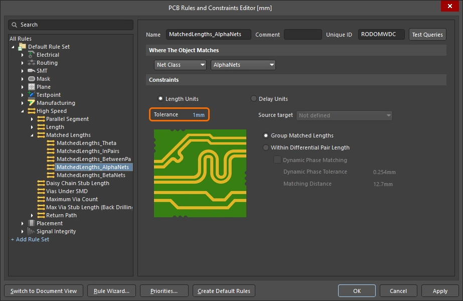 ). The set of nets that are targeted by the constraint is defined by the constraint scope or query.

The length tuning tool will either use the chosen Source target, or find the longest net in the set of target nets, and give you a valid range and target length (Value) of:
-
TargetLength = Longest routed net in set -
MinLimit = LongestNet - MatchedLength Constraint Tolerance -
MaxLimit = TargetLength
 )
) ).
). ).
).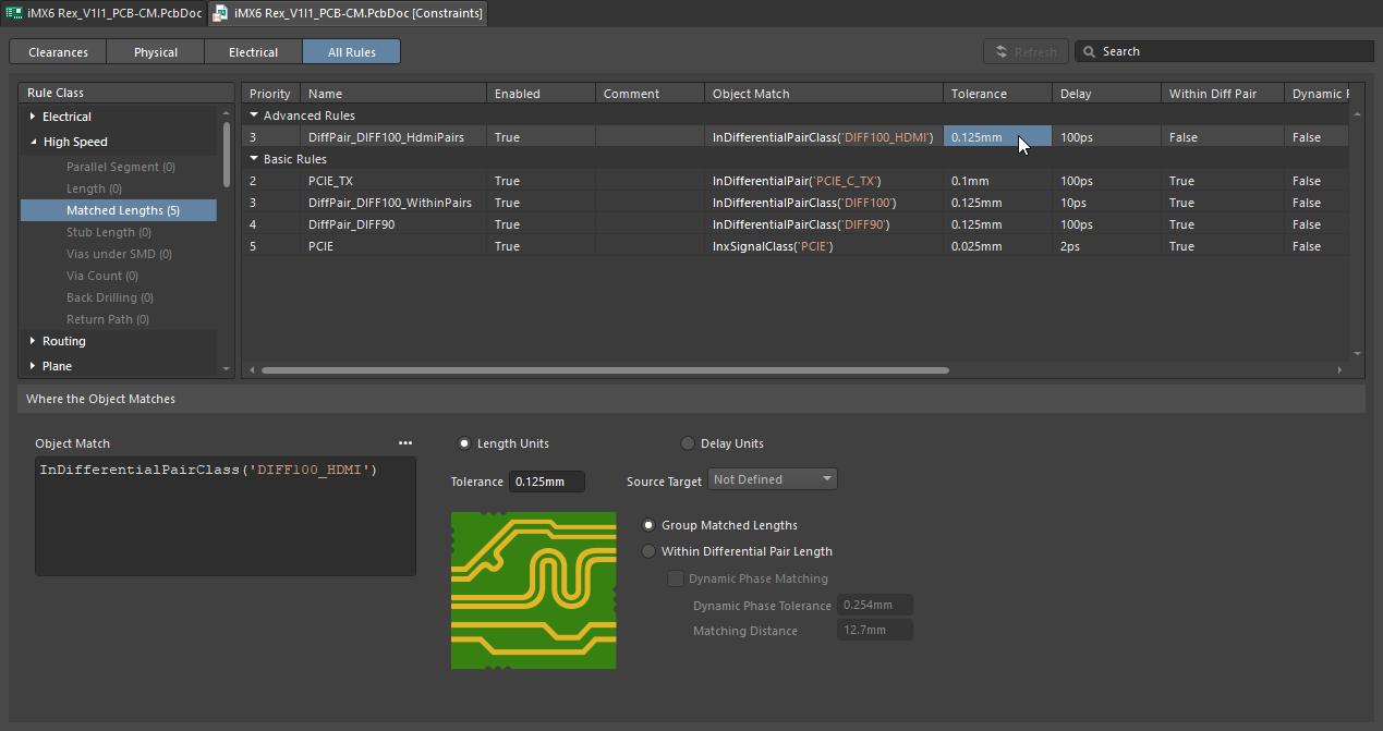 ).
).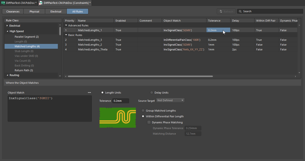 )
)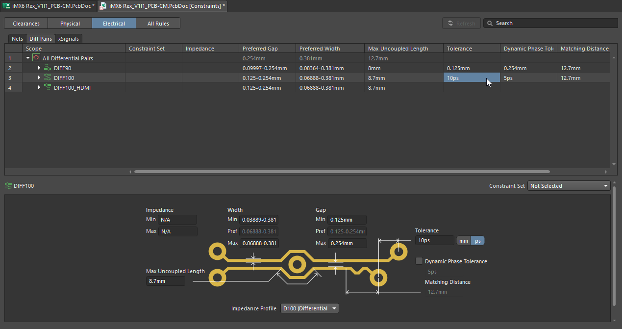 ).
).Learn more about the Matched Length constraint.
Length Design Constraint
Complementing the Matched Net Lengths constraint, the Length design constraint specifies the minimum and maximum permissible routed length of a net, or set of nets. Targeted nets must have a length within the specified Minimum and Maximum lengths (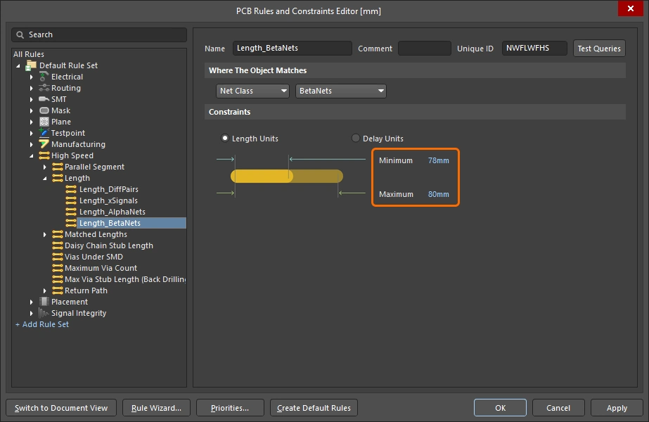 ).
).

The length tuning tool will find the longest net in the set of target nets and give you a valid range and target length (Value) of:
-
TargetLength = Longest routed net in set -
MinLimit = Constraint Minimum -
MaxLimit = Constraint Maximum
Learn more about the Length constraint.
How Overlapping Constraints are Resolved
Either or both of these constraints may be important in your design, it depends if your potential issues are related to skew (Matched Net Lengths constraint), or the overall signal delay (Length constraint).
If both of these constraints are being applied, the length tuning tool considers both and works out the tightest set of constraints.

The valid range and target length (Value) are determined as follows:
-
TargetLength = Longest routed net in set, or lowest MaxLimit from constraints -
MinLimit = (LongestNet - MatchedLength Constraint tolerance), or highest MinLimit from constraints -
MaxLimit = TargetLength -
ValidRange = Highest MinLimit to Lowest MaxLimit(most stringent combination of Length and Matched Length constraints)
For example, if the maximum length specified by the Length constraint is shorter than the longest existing route length identified by the Matched Length constraint, then the Length constraint wins and its shorter length is used during tuning. The panel displays the calculated Min Limit and Max Limit for each constraint, use these to check that the target lengths are what you are expecting.
In the image shown just above, a Length constraint and a Matched Length constraint apply to the target nets. Note that the most stringent values come from the Matched Net Length constraint (tolerance 0.5mm), the Max Limit value shows that the current length of the longest net in the target set of nets is 46.836mm (which is less than the maximum allowed by the Length constraint). In this example, the tightest allowable tolerance in the range of lengths is the tolerance defined in the Matched Length constraint (0.5mm), so it is used to calculate the ValidRange. The target length is always the more stringent maximum length.
Choosing the Tuning Pattern
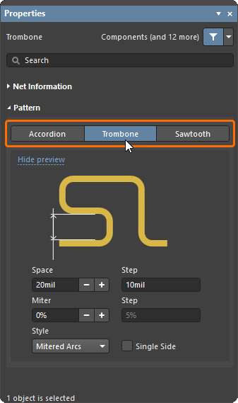
The tuning pattern must be chosen after launching the command, and before you commence length tuning.
To choose the tuning pattern:
-
Launch the Route » Interactive Length Tuning command.
-
Press
Tabto pause tuning and display the Properties panel. -
Select the required pattern (and edit the pattern settings if required).
-
Press the pause button
 to return to the Length Tuning command (or press the
 Esckey),ready to click on a net and tune its length.
| Can I change the pattern after starting to tune? | Once length tuning has been started (i.e. a route has been clicked on), the selected tuning pattern cannot be changed to another pattern. Right-click once to drop the route (or press Esc), you will remain in the Length Tuning command and then be able to press Tab, access the Properties panel, and change the pattern. |
| Can I change the pattern properties? | Pattern geometry properties can be configured in the Properties panel before you start tuning, at any time during tuning, or after tuning (select the pattern). Refer to the accordion, trombone and sawtooth geometry properties sections below to learn more. |
| What is the Step setting? | The Step field shows the amount that the associated value will change when you click the |
| What pattern and values are used next time? | The tuning pattern will default to the last-used pattern, with the last-used settings. |


Accordion Pattern Properties
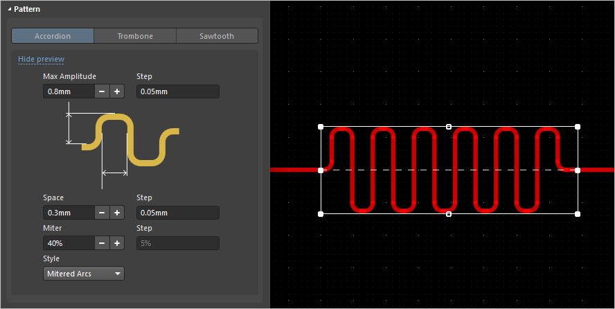
| Style | Style of the accordion corners, choose between Mitered Lines, Mitered Arcs, or Rounded. The Rounded style is the most compact and Mitered Lines is the least compact. |
| Max Amplitude | the maximum height (measured from the original route path) that the accordion can extend (it can be less than this, for example, to avoid an existing obstacle). To specify the units when entering a number, add the mm or mil suffix to the value. |
| Space | The distance between adjacent accordion switchback paths for the Mitered Lines or Mitered Arcs styles, and the Radius for the Rounded style. |
| Miter | Percentage that the corners of the tuning pattern are mitered when the Style is Mitered Lines or Mitered Arcs. This value is also used to miter the traces that connect the accordion to the route. |
Trombone Pattern Properties
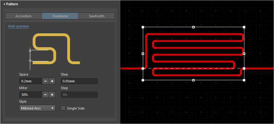
| Style | Style of the trombone corners, choose between Mitered Lines, Mitered Arcs or Rounded. The Rounded style is the most compact and Mitered Lines is the least compact. |
| Space | The distance between adjacent trombone switchback paths for the Mitered Lines or Mitered Arcs style or the Radius for the Rounded style. |
| Miter | Percentage that the corners of the tuning pattern are mitered when the Style is Mitered Lines or Mitered Arcs. |
| Single Side | Create the tuning pattern so that it only projects in one direction from the original route path. |
Sawtooth Pattern Properties
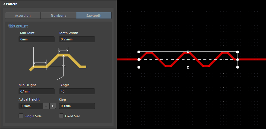
| Min Joint | Minimum length of the first colinear track segment placed before the first tooth is created. |
| Tooth Width | Width of the top of the tooth. |
| Min Height | Minimum allowable tooth height. |
| Angle | Slope of the leading and trailing tooth edges, relative to the original route path of the net being tuned. |
| Actual Height | Current tooth height, measured from the centerline of the original route path being tuned to the centerline of the tooth's top track segment. |
| Single Side | Create the tuning pattern so that it only projects in one direction from the original route path. |
| Fixed Size | Only allows each new tooth to be created at the Actual Height, preventing the creation of teeth that are not that size. If it is difficult to create sawtooth tuning, try disabling this option first. |
Tuning the Length of a Net
The elegance of the length tuning feature is that it cleverly combines sophisticated software algorithms with intuitive user control. Length tuning segments are added by simply wiping the cursor along the route path, with the dimensions and positions of the various tracks and arcs that make up the tuning segments automatically calculated and inserted by the length tuning algorithm. Keyboard shortcuts give you control over the style and properties of the tuning segments, as they are being added.
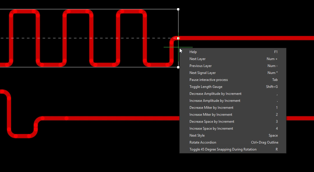
Use the shortcut keys to control the shape and amplitude of the tuning pattern during placement.
To tune the length of a net:
-
To perform length tuning based on constraints, configure the Matched Length and/or Length design constraints.
-
Launch the Interactive Length Tuning command from the Route menu (or the
 button on the Active Bar).
-
Press
Tabto open the Properties panel where you can select a length tuning pattern, then click the design space pause button () to resume placement.
-
Click on a route in the design space to start tuning its length. Move the cursor along the route in the direction that the accordion is to be added, a tuning pattern will appear and continue to grow as the cursor moves. The animation below shows examples of placing accordion tuning patterns.
-
To change the properties of the tuning pattern during length tuning, press Tab to open the Properties panel, or use the shortcut keys detailed below.
Shortcuts to Control the Pattern Properties during Tuning
 ).
).What Defines the Target Length of the Tuning Pattern?
During interactive length tuning, the Target section of the Properties panel includes options for selecting the required Target Length mode (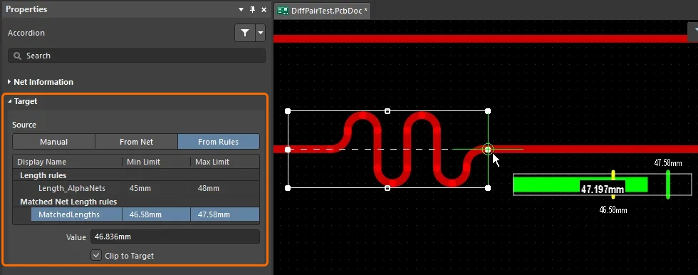 ). There are three modes available: manual (user-defined length), from net/pair (based on an existing net/pair length), or from rule (design constraint).
| Manual | Click the Manual button to enter the length in the Value field ( ). Recently Used Lengths are retained, in case you want to use one again. ). Recently Used Lengths are retained, in case you want to use one again. |
| From Net / From Diff Pairs | Click to display a list of already routed nets/differential pairs. Choose a net/differential pair to set the length Value ( ). ). |
| From Rules | Click to display a list of applicable Length and/or Matched Length design constraints ( ). The software will obey the most stringent combination of these constraints. Double-click on a constraint in the list in the panel to examine its properties in detail. To learn more about how the Length and Matched Length design constraints are applied when tuning a net, refer to the Configuring the Design Constraints section. The applied constraint is highlighted in blue. You can change the applied constraint as you tune by clicking that constraint's entry – it will become the constraint highlighted in blue, and the target length (and descriptive text) will change accordingly. ). The software will obey the most stringent combination of these constraints. Double-click on a constraint in the list in the panel to examine its properties in detail. To learn more about how the Length and Matched Length design constraints are applied when tuning a net, refer to the Configuring the Design Constraints section. The applied constraint is highlighted in blue. You can change the applied constraint as you tune by clicking that constraint's entry – it will become the constraint highlighted in blue, and the target length (and descriptive text) will change accordingly. |
| Value | The length that the tuning algorithm will attempt to achieve with the addition of tuning segments. Note there are a number of reasons that it may not be possible for the tuning algorithm to be able to add tuning segments, check out the Why Do the Tuning Patterns Disappear Sometimes? section to learn more. |
| Clip to Target | If enabled, the tuning algorithm will stop adding tuning shapes when the length is within Tolerance of the Value. |
Monitoring the Signal Lengths

When the PCB panel is set to Nets mode, it displays the current length of the routed signals. The default mode of the panel is to display the Name, Node Count, Routed length, and Unrouted (Manhattan) length. Right-click in the column headings region of the panel to display a menu, where you can select extra columns, as well as hide existing columns. Note that the Routed Length is calculated based on the sum of the lengths of the placed track and arc segments that form the routing, plus the vertical distance traversed through vias. The routed length calculator does not attempt to resolve overlapping track segments or routing wiggles inside pads.
For an accurate calculation of the total node-to-node distance, enable the Signal Length column. The signal length calculator analyzes all placed objects in the route path to resolve stacked or overlapping objects and wandering paths within pads, and includes via lengths. If the net is not completely routed the Manhattan (X + Y) length of the connection line is also included. Always ensure that the Signal Length column is enabled if you are preforming length matching.
If there are Matched Length or Length design constraints configured, the Signal Length cell of each net targeted by a constraint is also colored, highlighted in yellow if the route length < constraint minimum, clear if the net passes the constraint, or red if the route length > constraint maximum.
Learn more about the nets section of the PCB panel.
Using the Net Length Gauge
If there is a Length constraint and/or a Matched Length constraint defined, you can monitor the tuning length during interactive length tuning by displaying the Length Tuning Gauge. Use the Shift+G shortcut to toggle the Gauge on and off.
The Gauge shows the current Routed Length as a number, and the red/green slider shows the Estimated Length. If you are length tuning an existing route then the Estimated Length is the sum of all of the placed tracks and arcs (the actual physical length).
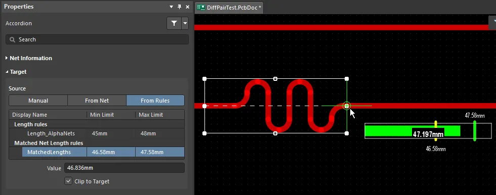
The Gauge settings are calculated from the constraints defined by the applicable constraints.
Understanding the Gauge |
|
| Green slider (and overlaid numerical value) |
Current route length, 47.197 in the example above |
| Left edge of gauge | Gauge minimum, 45 in the example above (lowest MinLimit) |
| Right edge of gauge | Gauge maximum, 48 in the example above (highest MaxLimit) |
| Left yellow bar | Highest MinLimit, 46.58 in the example above |
| Right yellow bar | Lowest MaxLimit, 47.58 in the example above (obscured by the green bar in the image) |
| Green bar | TargetLength , 47.58 in the example above (route length of the longest net in the set, equal to MaxLimit) |
Why Do the Tuning Patterns Disappear Sometimes?
The tuning engine builds tuning patterns according to the current geometry settings. There are combinations of these settings, along with the current track width, that can make it impossible for the tuning engine to create a tuning pattern.
If you are attempting to length tune and the patterns do not appear, try these steps:
-
Display the Properties panel as you work, so you can observe the various settings for the pattern (
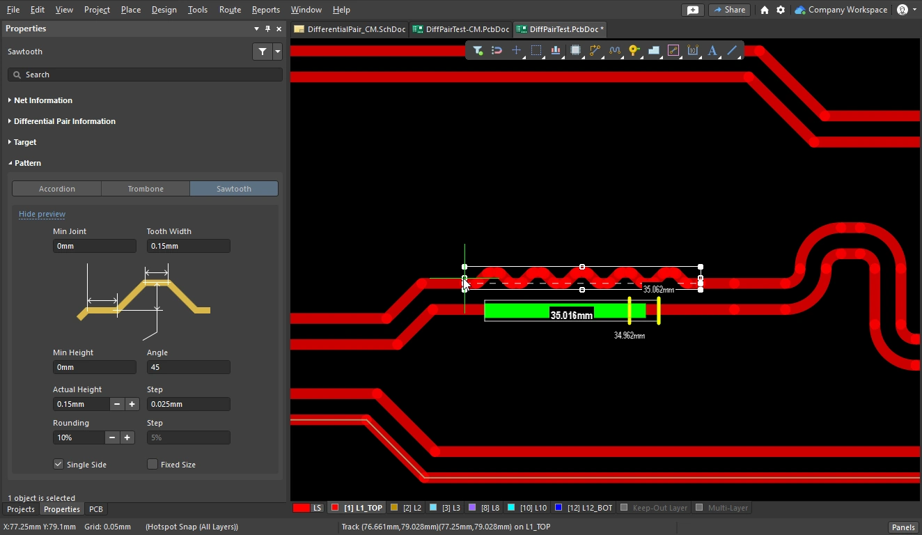 ). The
 F11shortcut can be used to toggle the Properties panel on and off. -
For the Accordion or Trombone patterns, make sure the pattern is in Mitered Lines mode (press the Spacebar to cycle through the modes).
-
For the Accordion or Trombone patterns, reduce the Miter to zero (press the 1 shortcut multiple times).
-
When you first click on a route to tune its length a white bounding rectangle appears, defining the space available for the tuning engine to create a pattern (
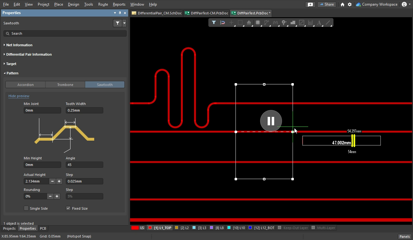 ).
).
-
If it extends a large distance beyond the adjacent routes, it may not be possible for the tuning engine to create a pattern (depending on other pattern settings). Press the
 < key multiple times to reduce the amplitude/height. Each press of that key will step the amplitude/height down by the current Step setting; a sensible value for the Step setting is around 1/10 of the Max Amplitude / Actual Height setting. If the Step setting is too large, press Tab on the keyboard to pause length tuning, enter a suitable Step value, and click the < button to resume length tuning.
-
If the bounding outline rectangle is too small when you start tuning, press the
 key to increase the amplitude/height to a sensible height.
-
-
For the Mitered Arcs Style, the current Miter setting also interacts with the Amplitude and Space settings. If you are using this Style, it can help to start with a small amount of Miter until you have found suitable Amplitude and Space values, then increase the Miter to the required amount.
-
The Sawtooth pattern includes a Fixed Size option, instructing the tuning engine to make all of the tuning patterns the same size (
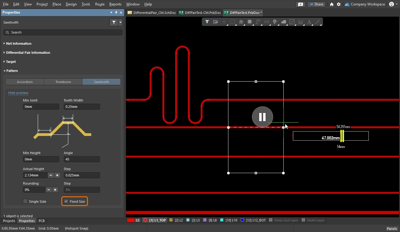 ). If your patterns are not appearing, try tuning this option off. If required, the option can be re-enabled once the length has been correctly tuned.
Modifying a Placed Tuning Pattern
To modify a placed tuning pattern, click once to select it and display the editing handles.
Resize the accordion bounding box to change the Amplitude or length, click and hold to move, edit the Style in the Properties panel.
Modifying a Placed Tuning Pattern |
|
| Change the style | Click to select a pattern (or patterns), then change the style and other settings in the Properties panel. The shortcuts can also be used, click and hold a selected tuning pattern to use them. |
| Move a pattern | Click and drag to move a pattern. While the accordion pattern does not support the sleeve concept so does not support placing or sliding around a corner, the Trombone and Sawtooth patterns do. Learn more about working with Trombone and Sawtooth patterns. |
| Resize the pattern | Click and drag on an edge or vertex to resize the pattern bounding region – the pattern sections are automatically resized to suit the new updated shape of the bounding region. |
| Rotate an accordion | Select the accordion, hold down
|
| Change the layer | The Properties panel of a placed tuning pattern selected in the design space includes the Layer drop-down in its Properties region. Use this drop-down to quickly change the signal layer where the tuning pattern is placed ( ). Note that you can select multiple routing objects (tuning pattern, tracks, arcs) and change their signal layer in a single action. ). Note that you can select multiple routing objects (tuning pattern, tracks, arcs) and change their signal layer in a single action. |
Working with Placed Trombone and Sawtooth Patterns
For the Trombone and Sawtooth patterns, the polygonal area that the pattern is constructed within can be thought of as a sleeve. Click to select a placed pattern and display the sleeve.
There a number of different movement and size-change behaviors available, depending on where you click and hold on the sleeve. There are three zones where you can click and drag, as shown in the color-enhanced image shown below:
 The trombone and sawtooth patterns are built within a sleeve shape, which supports a variety of shape-change editing behaviors.
Modifying a Trombone or Sawtooth Pattern ( ) |
|
| Move the pattern | Click and Drag on Zone 3 to freely move the pattern perpendicular to the original route path. Hold Shift to maintain the pattern's lateral distribution across the route path. |
| Lengthen or widen the pattern | Click and Drag on Zone 1 or 2 to lengthen or widen the pattern. Note that it is not necessary to click on a handle to resize the pattern; use anywhere along the sleeve edge. |
| Maintain lateral distribution during movement | Shift + Click and Drag on Zone 1 or 3 to slide the pattern along the original route path, maintaining the pattern's lateral distribution across the route path. |
| Perpendicular pattern movement | Ctrl + Click and Drag on Zone 2 or 3 to move the pattern perpendicular to the original route path. |
Length Tuning Differential Pairs
There are two aspects to length tuning differential pairs: the first is tuning the lengths of each pair in a set so that all of the pairs are the same length; the second is tuning the length of the shorter net within each pair, a process referred to as phase matching.
To length tune differential pairs, create the following constraints to target the set of differential pairs:
-
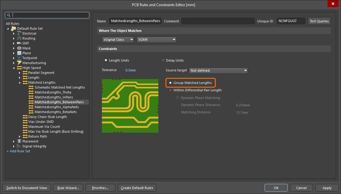
A matched length constraint that defines the length matching requirements between pairs. To test the length of one pair against the length of another pair enable the Group Matched Lengths option, as described in the Matched Length Design Constraint section above.
-
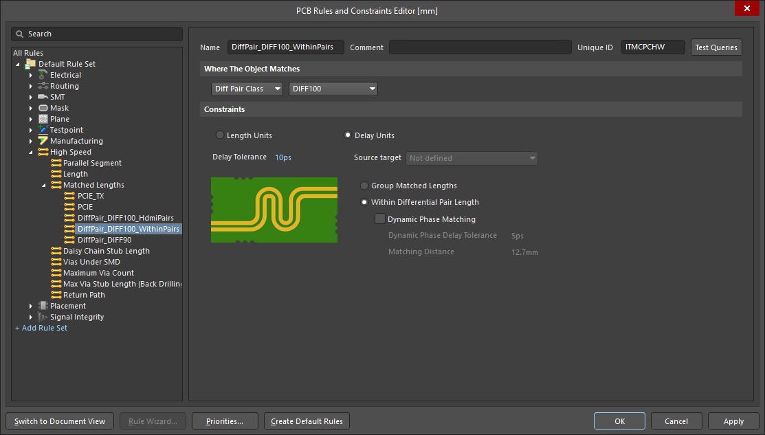
A second matched length constraint that defines the within-pair length matching requirements. To test the length of one pair-member against the other pair-member enable the Within Differential Pair Length option, as described below.
Length Tuning between the Differential Pairs
Once the differential pairs have been routed, any difference between the pair lengths can be matched.
Demonstration of tuning the lengths of the pairs, then tuning the lengths within each pair.
Length Tuning Between Pairs |
|
| Targeting the pairs | Typically the pairs are targeted by the Matched Length design constraint using one of the Differential Pair query keywords - InAnyDifferentialPair, InDifferentialPair, InDifferentialPairClass, IsDifferentialPair. To match the lengths between pairs, enable the Group Matched Lengths option in the Matched Length design constraint ( If you have defined xSignals these can be used to scope the length tuning design constraints, and the Source Target option will become available in the constraint. Refer to the Defining High Speed Signal Paths with xSignals page to learn more. |
| What is the target length? | The Matched Length design rule detects the longest pair targeted by the rule scope and uses the Longest Signal Length value of that pair as the Max Limit for the other targeted pairs, setting the Min Limit to |
| Tune the length of a pair | To tune the length of a pair, run the Route » Interactive Differential Pair Length Tuning command. As with differential pair routing, this command operates on the two nets in the pair simultaneously. Learn more about tuning the length of a net. |
| Controlling the shape during tuning | As with single-net length tuning, after launching the length tuning command you must select the tuning style before clicking on a route. During length tuning, the properties of that style can be changed using the shortcuts, or by pressing Tab to access the Properties panel. |
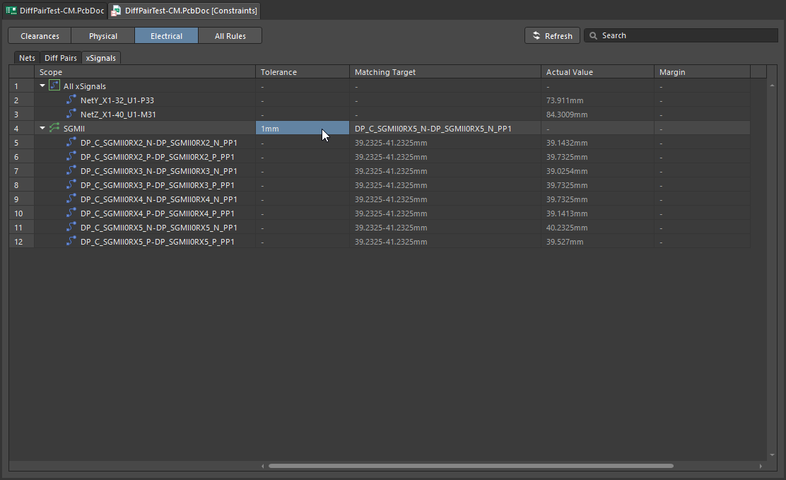
| Monitoring the progress | During length tuning, use the You can also monitor the progress in the PCB panel, in Nets mode or xSignals mode ( |
| Adjusting the finished tuning shape | Tuning shapes are objects, they can be selected, dragged, resized and deleted. Learn more about modifying a placed tuning pattern. |
| Checking the results | Use the PCB Rules and Violations panel to check the between-pair Matched Net Length constraint(s) (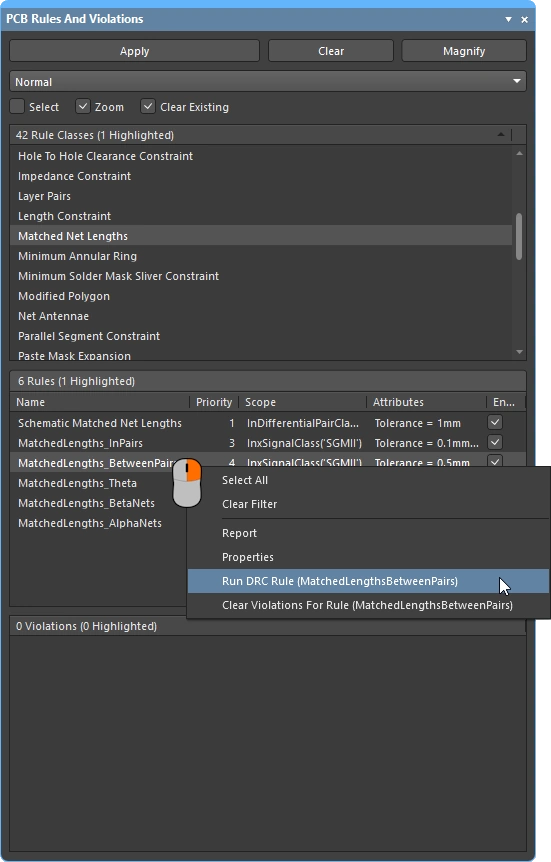 ). Adjust the tuning accordions if required. ). Adjust the tuning accordions if required. |
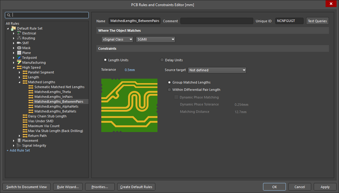 ).
).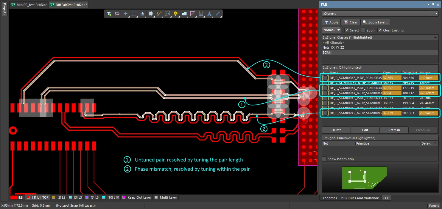 ).
).Static Phase Matching for Differential Pairs
Given the inherently poor differential coupling that can be achieved when a signal pair is implemented as routing on a printed circuit board, matching the lengths of the two nets in the pair plays a critical role in the overall effectiveness of differential pair routing.
Length matching ensures that the positive and negative sides of the pair arrive at the same time, a technique referred to as phase matching. The simplest approach to match the phase is to add a length tuning shape somewhere along the length of the shorter net in the pair. This type of length tuning is referred to as static phase matching, meaning, the overall lengths match, but there has been no attempt made to resolve the length mismatch as it occurs along the path of the differential route.
Demonstration of tuning the lengths within each pair.
Static Length Tuning Within the Pair |
|
| Targeting the pairs | Typically the pairs are targeted by the Matched Length design constraint using one of the Differential Pair query keywords - InAnyDifferentialPair, InDifferentialPair, InDifferentialPairClass, IsDifferentialPair. To match the lengths with each pair, enable the Within Differential Pair Length option in the Matched Length design constraint (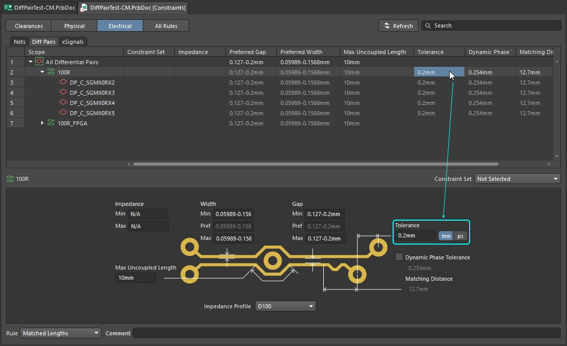 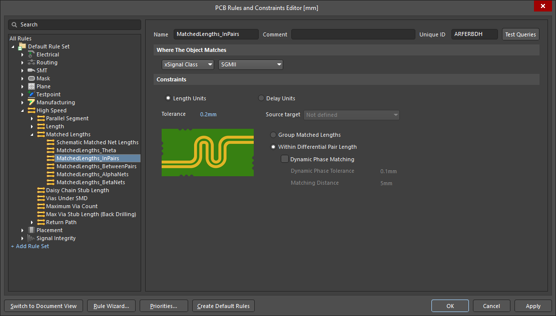 ). Configure the tolerance as required. ). Configure the tolerance as required. |
| Tune the length of the shorter net in the pair | To tune the length of the shorter net in the pair, run the Route » Interactive Length Tuning command. Learn more about tuning the length of a net. |
| Controlling the shape during tuning | After launching the length tuning command you must select the tuning style before clicking on a route. During length tuning, the properties of that style can be changed using the shortcuts, or by pressing Tab to access the Properties panel. |
| Monitoring the progress | During length tuning, use the You can also monitor the progress in the PCB panel, in Nets mode or xSignals mode ( |
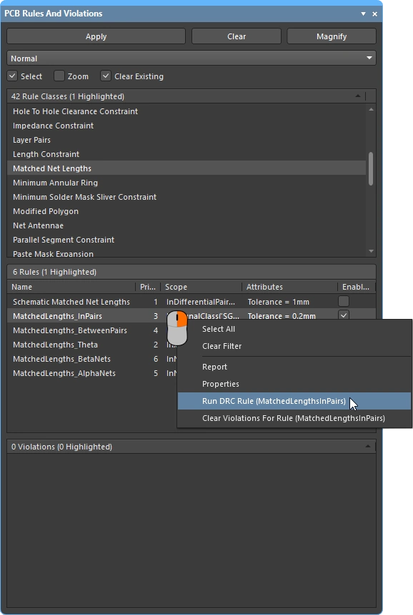
| Checking the results | Use the PCB Rules and Violations panel to check the within-pair Matched Net Length constraint(s) ( |
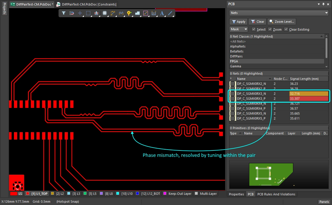 ).
). ).
).Automatic Length Tuning
The PCB editor also supports automatic length/delay tuning (or multi-tuning), for both single nets and differential pairs. Regular traces and odd angles (apart from differential pairs at odd angles) are also supported.
The Auto Tuning process will attempt to tune the lengths of the currently selected nets, in accordance with the applicable Matched Length / Length design constraints. Refer to the Configuring the Design Constraints section to learn more.
Lengths can be automatically tuned, both between nets and pairs, and also within each pair.
The functionality is used as follows:
Automatic Length Tuning Between Nets ( |
|
| Configure how lengths are matched | Configure the Length / Matched Length (with the Group Matched Length option enabled) design constraint for the nets / diff pairs / xSignals as required. |
| Select nets to be matched | Select the nets whose lengths are to be tuned. |
| Configure the length matching pattern | Select the Route » Automatic Length Tuning command (shortcut: Select the accordion-based pattern style and configure its attributes as required. Refer to the Choosing the Tuning Pattern section to learn more. |
| Auto tune the lengths | Click OK in the Auto Tuning Process dialog and the software will attempt to create the tuning patterns. |
 )
)| Configure how lengths are matched | Configure the Length / Matched Length (with the Within Differential Pair Length option enabled) design constraint for the nets / diff pairs / xSignals as required. |
| Select nets to be matched | Select the nets whose lengths are to be tuned. |
| Static phase matching | Static matching is applied when the Dynamic Phase Matching (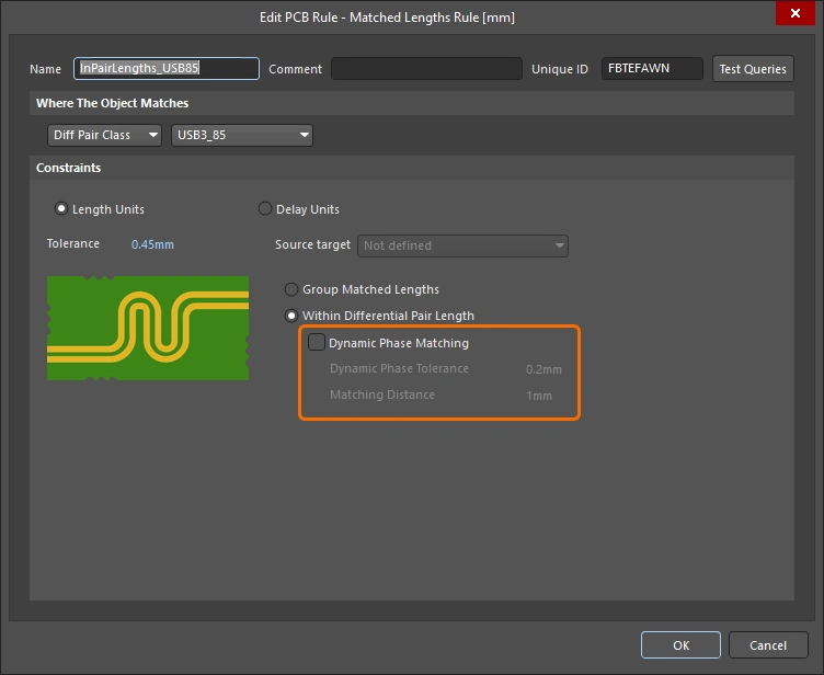 ) / Dynamic Phase Tolerance ( ) / Dynamic Phase Tolerance (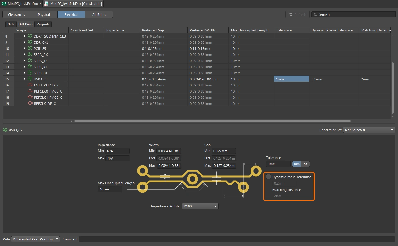 ) option is disabled in the Matched Length constraint. Tuning patterns are added anywhere along the length of the shorter net in the pair. ) option is disabled in the Matched Length constraint. Tuning patterns are added anywhere along the length of the shorter net in the pair. |
| Dynamic phase matching | Dynamic matching is applied when the Dynamic Phase Matching (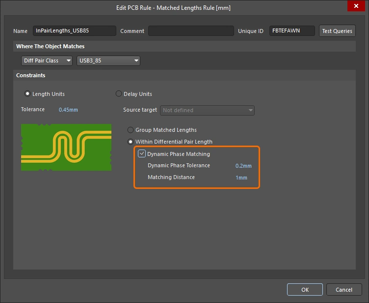 ) / Dynamic Phase Tolerance ( ) / Dynamic Phase Tolerance (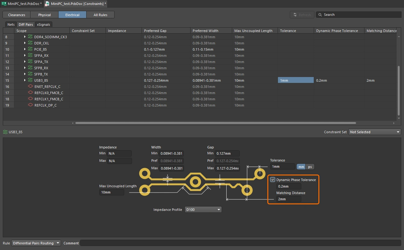 ) option is enabled in the Matched Length constraint. Tuning patterns are typically added at multiple points along the shorter net in the pair. ) option is enabled in the Matched Length constraint. Tuning patterns are typically added at multiple points along the shorter net in the pair. |
| Configure the within pair Sawtooth tuning properties | Select the Route » Automatic Length Tuning command (shortcut: Configure the attributes of the sawtooth pattern style as required. Refer to the Sawtooth Tuning Pattern section to learn more. |
| Auto tune the lengths | Click OK in the Auto Tuning Process dialog and the software will attempt to create the phase tuning patterns. |
 )
)Other Tuning Tools
Converting a Tuning Pattern into Primitives
A length tuning pattern, being a union, is a group object – comprised of primitive track and/or arc segments, with full control over the amplitude, gap, and corner radius (or miter). As with other group objects, such as components, dimensions, and polygons, a length tuning pattern can be exploded. In other words, it can be converted into its constituent-free primitives, which can then be modified independently. Use the Explode Length Tuning to Free Primitives command to do this, available from the main Tools » Convert sub-menu, or the right-click Unions sub-menu.
Note that exploding any object in the PCB editor is a one-way process, once an object has been exploded it cannot be converted back into that object-kind. You can only use the Undo command to achieve this.
Equalizing Net Lengths
The Tools » Equalize Net Lengths command from the main menus of the PCB editor can be used to match the length of nets identified by a defined Matched Net Lengths design constraint. After launching the command, the Equalize Nets dialog will open.

Use this dialog to define the style and sizing of the accordion segments that will be added by the software to equalize the lengths of the target nets. After clicking OK, track segments will be added to all nets in the set covered by the design constraint that are shorter than the longest net in the set. The command will attempt to add track to these shorter nets until the specified tolerance condition in the relevant Matched Net Lengths constraint has been met.
A design rule check will be performed for all defined (and enabled) Matched Net Lengths constraints only and the Design Rule Verification Report (Design Rule Check - <PCBDocumentName>.html) will be opened as the active document. The report will list any violations of these constraints. For information about how far outside of the tolerance each net in the applicable set is, refer to the relevant message in the Messages panel, an example of which is shown below:
Matched Net Lengths: Between Net LCD_RW And Net LCD_RS Length:85.061mm, outside tolerance by 7.564mm
In this case, the longest net in the set targeted by the applicable Matched Net Lengths constraint is LCD_RS. The net LCD_RW has a routed length of 85.061mm, which is outside of the tolerance defined by the constraint by 7.564mm.
Suggested Reading
-
Website for Eric Bogatin, signal integrity lecturer and industry expert http://www.bethesignal.com/
-
Website for Dr. Howard Johnson, high-speed design lecturer and industry expert http://www.signalintegrity.com/
-
Website for Lee Ritchey, lecturer and high-speed PCB design expert http://www.speedingedge.com/