KB: Draftsman Board Section View Cut Extents cannot be adjusted
 Altium Designer
Solution Details
Cutting line nodes cannot be dragged
In a Draftsman document, a placed Board Section View shows its cutting line, but the end nodes cannot be dragged. As a result, the section view always represents a full cut through the entire board instead of a limited region. This happens even though the cutting line nodes are visible and the view was created successfully.
Document snapping affects graphical editing
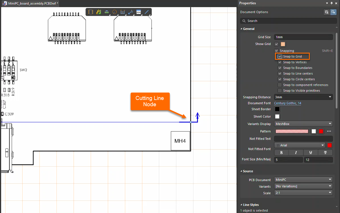
Graphical editing of Draftsman views depends on the document’s grid and snapping configuration. If Snap to Grid is disabled, interactive editing operations—such as dragging Board Section View cutting line nodes—may not function correctly. In addition, the Board Section View must be selected in the design space for its editing nodes to become active.
Enable snapping at the document level
- Enable Snap to Grid in the Draftsman document properties to allow cutting line nodes to be dragged.
This setting applies at the Draftsman document level, not per individual view, which explains why reopening the file or restarting Altium Designer alone does not resolve the issue.
Enable Snap to Grid and adjust cut
- Open the Draftsman document containing the Board Section View.
- Ensure no object is selected so the Draftsman Document Properties panel is shown.
- In the properties panel, enable Snap to Grid.
- Select the Board Section View in the design space.
- Click, hold, and drag one of the cutting line end nodes to adjust the section cut extents.