KB: Rigid region incorrectly flagged as flex when enabling 3D Locked

Altium Designer Altium Designer
In rigid‑flex PCB designs, a rigid board region may be incorrectly treated as flex when enabling the 3D Locked option, most often after redefining the board outline or modifying regions. This issue is not caused by the board geometry, but by the layer stack assigned to the region. If the assigned layer stack or substack has the Is Flex option enabled in the Layer Stack Manager, Altium Designer will always treat the region as flex and disable 3D locking. Assigning rigid regions to a layer stack with Is Flex disabled resolves the issue.

Solution Details

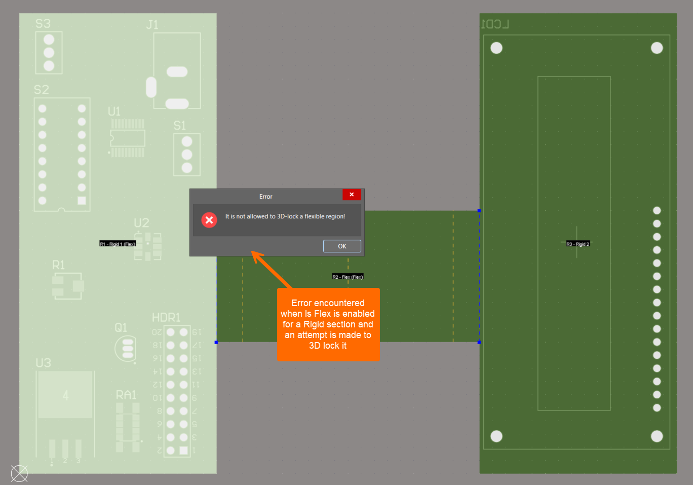
Rigid region cannot be locked in 3D

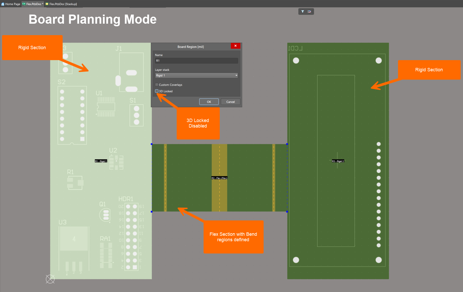
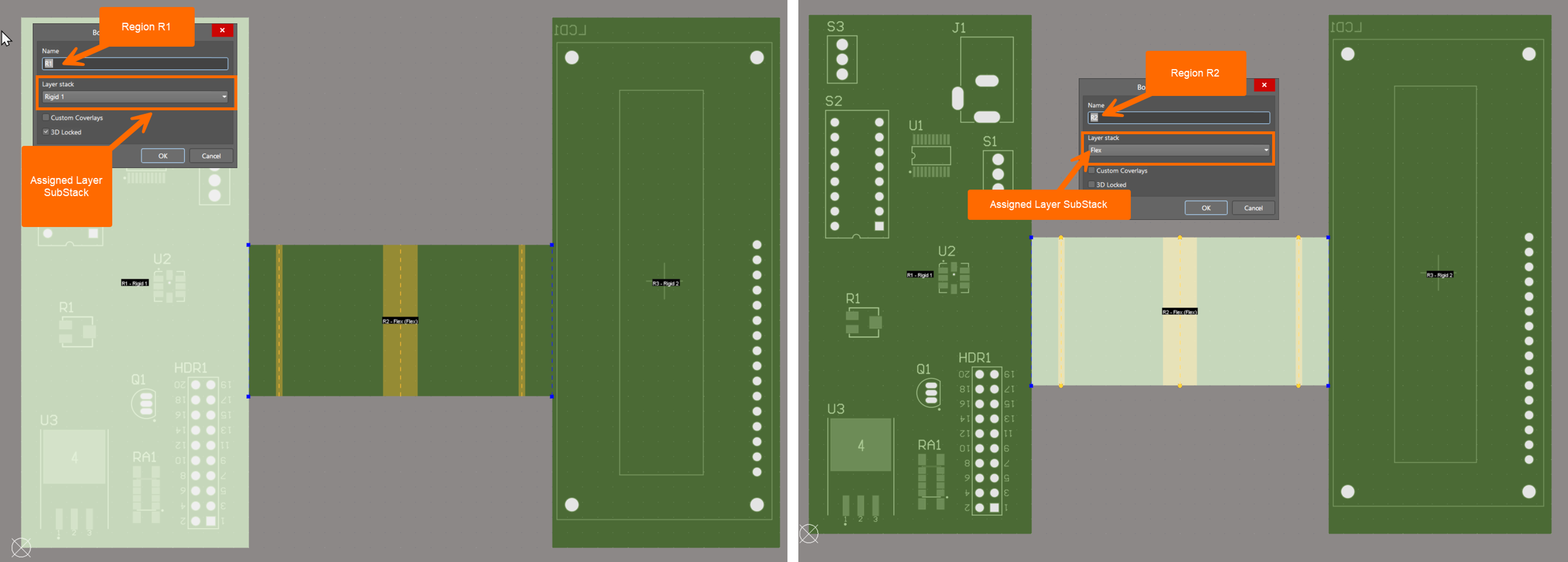
After redefining the board outline, Board Planning Mode appears normal: split lines snap correctly, regions can be named, and layer stacks can be assigned. Flex regions display yellow bending lines as expected. However, when editing a rigid region, the 3D Locked option is unavailable because the region is interpreted as flex.

Altium Designer PCB editor showing a rigid‑flex board with a central flex region and an error dialog stating “It is not allowed to 3D‑lock a flexible region,” indicating an attempt to enable 3D Lock while the region is set as flex.

Altium Designer Board Planning Mode showing a rigid‑flex PCB with two rigid regions and a central flex section with bend regions, and a Board Region dialog where the rigid layer stack is selected and the 3D Locked option is disabled.

Layer stack defines rigid or flex behavior

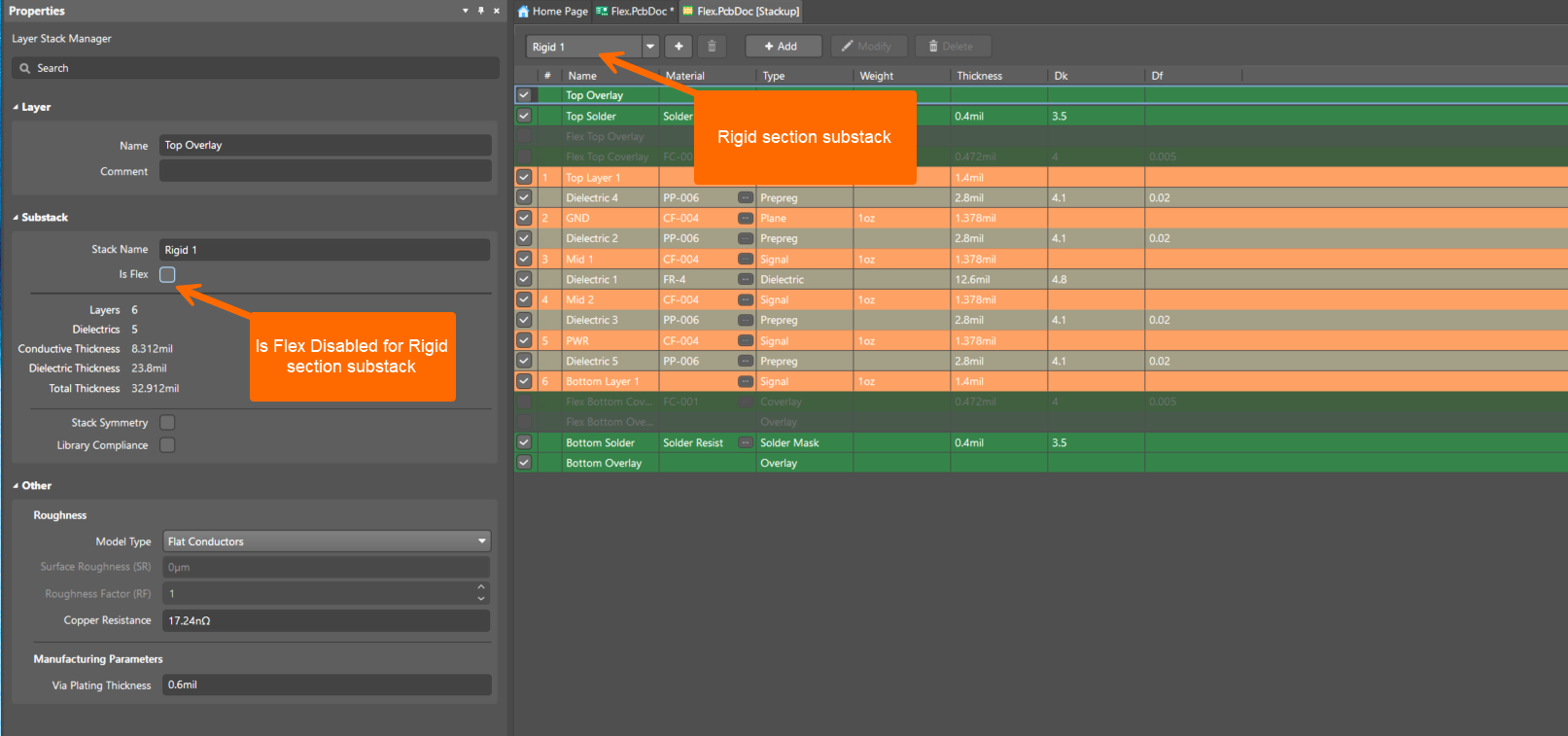
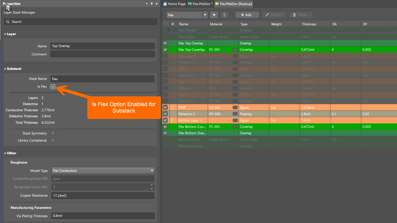
Whether a board region is treated as rigid or flex is determined solely by the assigned layer stack or substack. If the Is Flex option is enabled, the region is always treated as flex. The 3D Locked option is available only for regions assigned to rigid substacks, by design. The selected rigid‑flex design mode (Standard or Advanced), configured in the Layer Stack Manager, can also influence region behavior after board outline changes.

Altium Designer Layer Stack Manager showing a Flex substack with “Is Flex” enabled, listing flex overlay, signal, dielectric, and coverlay layers with thickness and material details, confirming the substack is configured as a flexible stack.

Assign correct rigid and flex substacks

  • Assign rigid regions only to substacks with Is Flex disabled.
  • Assign flex regions only to substacks with Is Flex enabled.
  • Use separate rigid and flex substacks that differ only by the Is Flex setting.
  • After redefining the board outline or re‑slicing regions, recheck all substack assignments.

Altium Designer Board Planning Mode showing two board regions with different layer stacks: Region R1 assigned a rigid substack and Region R2 assigned a flex substack, illustrating correct rigid and flex region assignment in a rigid‑flex PCB.

Disable Is Flex for rigid stack

  1. Open Design » Layer Stack Manager.
  2. Select the layer stack or substack used by the rigid region.
  3. In the Properties panel, clear the Is Flex option.
  4. Verify the correct rigid‑flex design mode is enabled.
  5. Return to Board Planning Mode.
  6. Edit the rigid region and enable 3D Locked.

Altium Designer Layer Stack Manager showing the Rigid 1 substack selected, with Is Flex unchecked, listing rigid signal, plane, dielectric, solder mask, and overlay layers with thickness values, confirming the region is configured as rigid.

References

如您发现任何问题,请选中相关文本/图片,并按 Ctrl + Enter 键向我们提交反馈。