
KB: STEP Export Does Not Include Copper or Overlay
Solution Details
Overlay and copper missing in STEP output
After exporting a PCB document using STEP, the 3D model shows only the board body and component 3D models. Silkscreen, copper tracks, pads, pours, and text markings are not visible. This applies whether 3D bodies are defined in component footprints or placed directly in the PCB document as free 3D Body objects.
STEP format limitations by design
STEP is intended for exchanging mechanical geometry between ECAD and MCAD tools. By design, STEP export from Altium Designer does not include electrical or graphical PCB layers such as copper or silkscreen. This behavior is consistent across modern Altium Designer installations and is not controlled by export options or license configuration.
Available alternatives when copper or overlay is required
- Use STEP as intended: Export the board outline, thickness, component 3D bodies, and pad holes only when copper or overlay visibility is not required for the mechanical task.
- Export to Parasolid: Use Parasolid export when a static 3D file with copper geometry is required. This produces true 3D copper but can result in very large files.
- Use Altium MCAD CoDesigner: For modern ECAD–MCAD collaboration, use Altium MCAD CoDesigner to synchronize PCB data directly with supported MCAD tools. Depending on available ECAD–MCAD features, this can include accurate 3D copper geometry and overlay representation.
- Legacy workflow (not recommended): Older legacy tools exposed in Altium Designer 17 allowed copper and silkscreen to be embedded into STEP files. This approach is deprecated and may generate extremely large files that are difficult to open in MCAD tools.
How to export based on your use case
- For standard mechanical exchange, use File » Export » STEP 3D and enable Pad Holes if hole geometry is required. Expect no copper or overlay in the result.
- If copper geometry must be included in a static 3D file, use File » Export » PARASOLID and select the appropriate copper export options. Be aware that file size and complexity may increase significantly.
- For ongoing ECAD–MCAD collaboration, use Altium MCAD CoDesigner to push and pull PCB data between Altium Designer and supported MCAD software.
- If working with a legacy installation, note that Altium Designer 17 exposed a legacy export via Tools » Legacy Tools » Legacy 3D View Tools » Export, where Silkscreen, Text, and Copper could be selected. This method is provided for historical reference only and is not recommended.
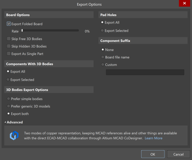
STEP Export Options
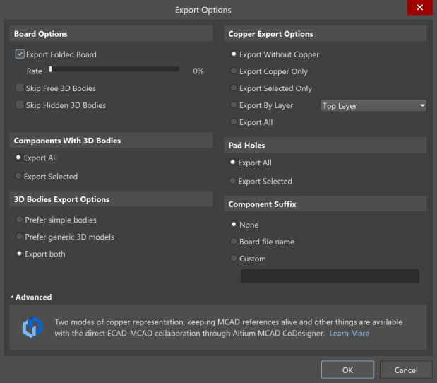
Parasolid Export Options
Additional Notes
STEP export limitations are expected and working as designed. If copper or overlay markings are required in 3D, STEP is not the appropriate format. Use Parasolid export for static geometry or Altium MCAD CoDesigner for collaborative ECAD–MCAD workflows.
References
Refer to Altium Designer documentation for ECAD–MCAD collaboration and Parasolid export: