
KB: Position 3D Body model precisely in PCB footprint library
Solution Details
Positioning a 3D body model to align with the rest of a footprint involves 6 steps:
1 In the .PcbLib with the footprint in view, Place a 3D Body and select a 3D model (STEP, Parasolid, and Solidworks Part file) to embed in the 3D Body: Place » 3D Body » Select file » Open.
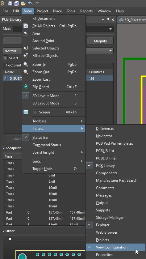
2 Enable the visibility of 3D Body Reference Point / Custom Snap Points in the View Configuration Panel using the Panels button in the lower-left corner of Altium Designer.
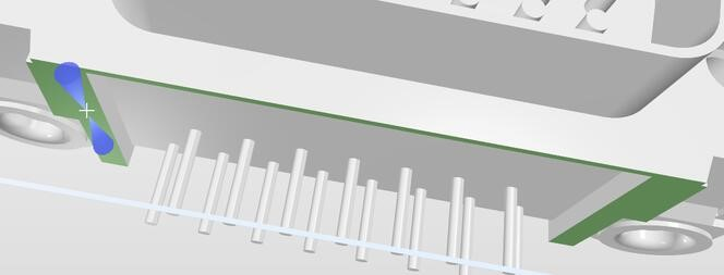
3 Hit 3 to enter 3D View of the Footprint and orient the view so that the face of the 3D model that needs to be in contact with the Boards Surface is in view. This is done using Shift + Right Click + Move Mouse to orient the view.
4 Tools » 3D Body Placement » Align Face With Board to choose a face to coincide with board surface.
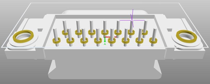
5 Tools » 3D Body Placement » Add Snap Points From Vertices to add a reference point to snap for horizontal alignment
6 Hit 2 to switch to 2D layout mode, and drag and drop the reference point to the target.
1 Specify a Model to place 3D Body
In the .PcbLib with the footprint in view, Place a 3D Body and select a 3D Step Model to embed in the 3D Body. Supported models types are STEP, Parasolid, and Solidworks Part file):
Place » 3D Body » Select file » Open
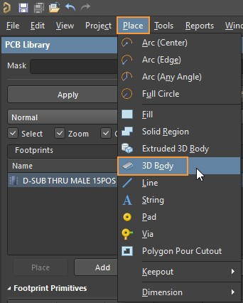

Place the 3D Body into the Footprint with a Left Click and then Right Click to exit placement of additional 3D Body.
2 Enable the visibility of 3D Body Reference Point / Custom Snap Points
In the View Configuration Panel using the Panels button in the lower-left corner of Altium Designer or
View » Panels » View Configuration from the file menu.
Expand the System Colors section in the Layer & Colors tab of the View Configuration Panel

3 Orient 3D Model in 3D View for Alignment
Enter 3D View of the Footprint from View » 3D Layout Mode or use the 3 key on your keyboard
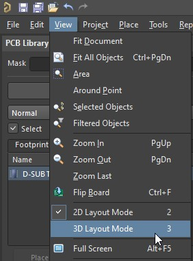
Orient the view in 3D so that the Face of the 3D Model that needs to be in contact with the Boards Surface is in view. This is done using Shift + Right Click + Move Mouse to orient the view.

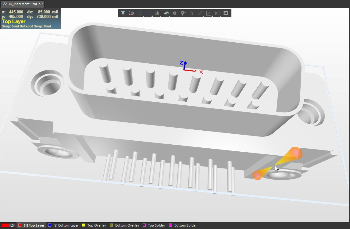
4 Align the bottom surface of Step Model with the Top Surface of the PCB
Tools » 3D Body Placement » Align Face With Board
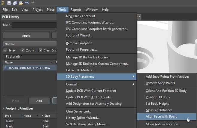
Pick a 3D Body as indicated in the Status Bar down at the bottom of the Altium Designer. If you do not see the Status Bar use View » Status Bar so that it is in view


Choose Face of the 3D Step Model that needs to be in contact with the surface of the PCB as indicated in the Status Bar

5 Create a Snap Point in the Center of Pin for precise Pin to Hole alignment.
Use 0 on the Numeric Keypad to view the bottom of the model and then use Shift + Right Click + Move Mouse to orient the model so that you have a clear view of both sides of a single pin. And then Tools » 3D Body Placement » Add Snap Points From Vertices
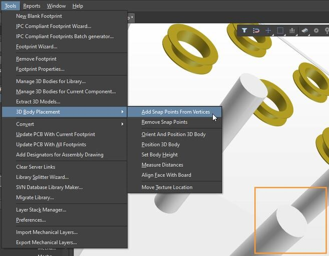
Select the Step Model as indicated in the Status Bar

Press the Spacebar to enter Midpoint Mode
Refer to the Status Bar for instructions:
‘Pick vertex 1 of 2. The snap point will be placed at their midpoint’


Select a Vertice on one side of a pin and observe the Status Bar for instructions:
‘Pick vertex 2 of 2. The snap point will be placed at their midpoint’
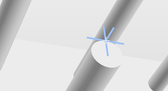

Select a Vertice on the opposite side of a pin and Right Click after to exit Snap Point creation.
creation. Observe the Snap Point that has been created in the center of the Pin.

6 Align Pin to Hole using Snap Point in 2D
View » 2D Layout Mode or use the 2 key on Numeric Keypad to enter 2D Mode
Select the 3D Body by the Snap Point newly created in 3D Mode which can be seen in 2D Mode and move the 3D Body into position by snapping to the appropriate pin.


Use the 3 key on Numeric Keypad to enter 3D Layout Mode to find your model with pins precisely aligned with holes of the footprint
Further details on related topics can be found in:
Working with 3D Bodies
Additional Tools for Working with 3D Bodies