
KB: Schematic and PCB Not Syncing - Differential Pair Routing Error Second differential pair primitive could not be found.
Solution Details
Problem: Differential Pair Classes Not Updating in PCB
Issue Overview
When updating the PCB from the schematic, differential pairs or their classes may not transfer correctly. The ECO process continuously attempts to add Differential Pair Class Members to the PcbDoc, but routing the affected pairs results in an error.
Why This Happens
The root cause of this repeated ECO update failure is currently unknown. The system fails to assign both nets to the differential pair, causing routing errors despite the pair appearing in the Differential Pair Editor. Additionally, synchronization issues may occur if schematic directives are incomplete or incorrectly defined. Altium requires both nets to be explicitly assigned for successful transfer and routing.
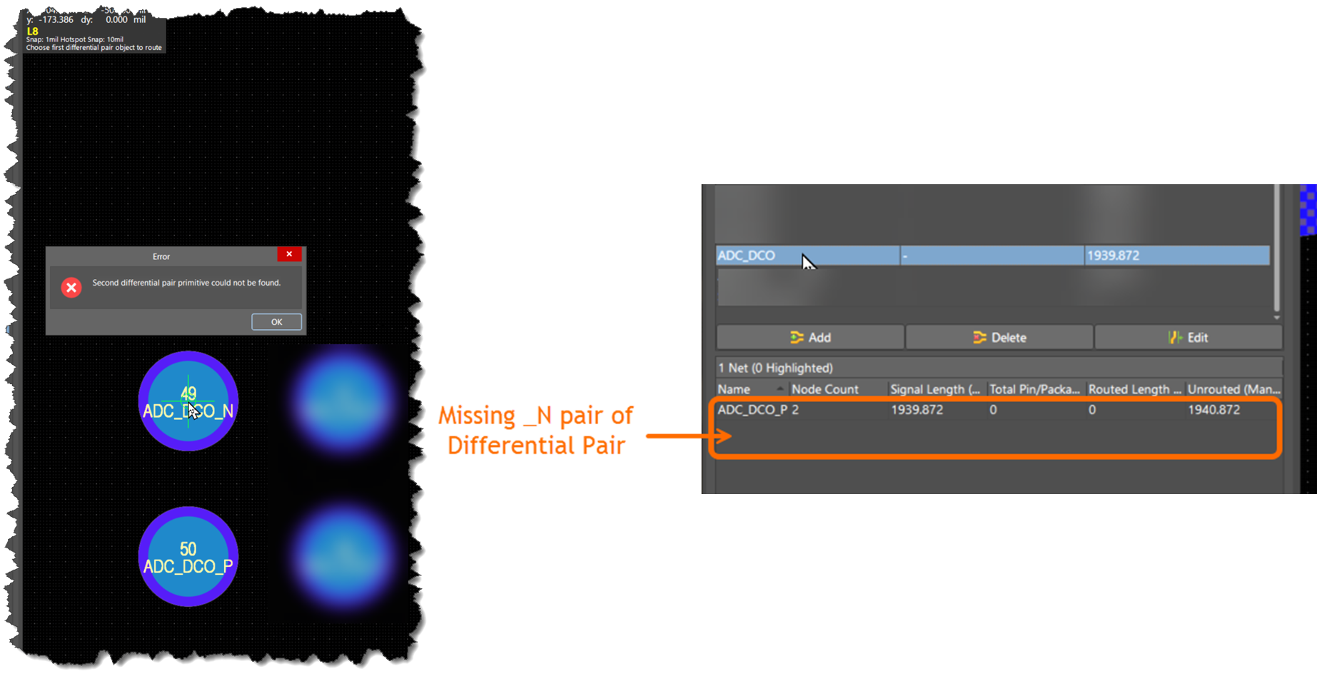 |
| Error when an attempt is made to route the differential pair. PCB panel showing the missing Negative Net for the defined Differential pair |
What to Do
To resolve the issue, apply one of the following workarounds:
- Delete and recreate the affected differential pairs from the schematic.
- Manually assign missing nets in the PCB Panel using the Differential Pair Editor.
How to Do It
Option 1: Delete and Recreate Differential Pairs
- Delete differential pair labels and directives in the schematic
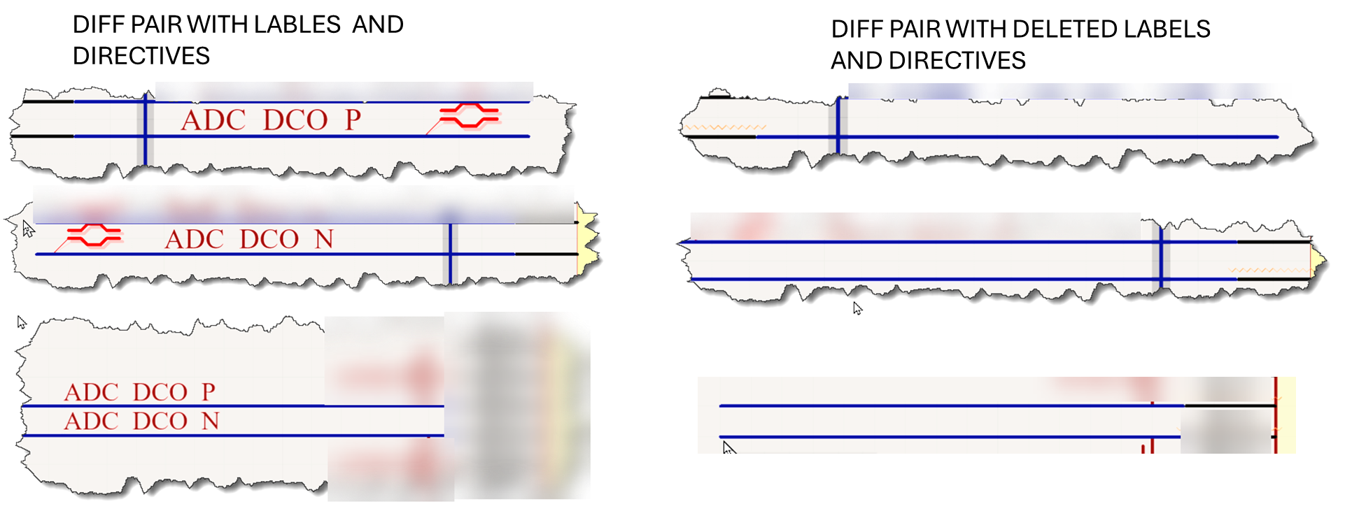
Delete labels and directives for the affected differential pairs -
Update the PCB using: Design » Update PCB Document or Design » Import Changes from…
- Confirm the affected pairs are removed from the design.
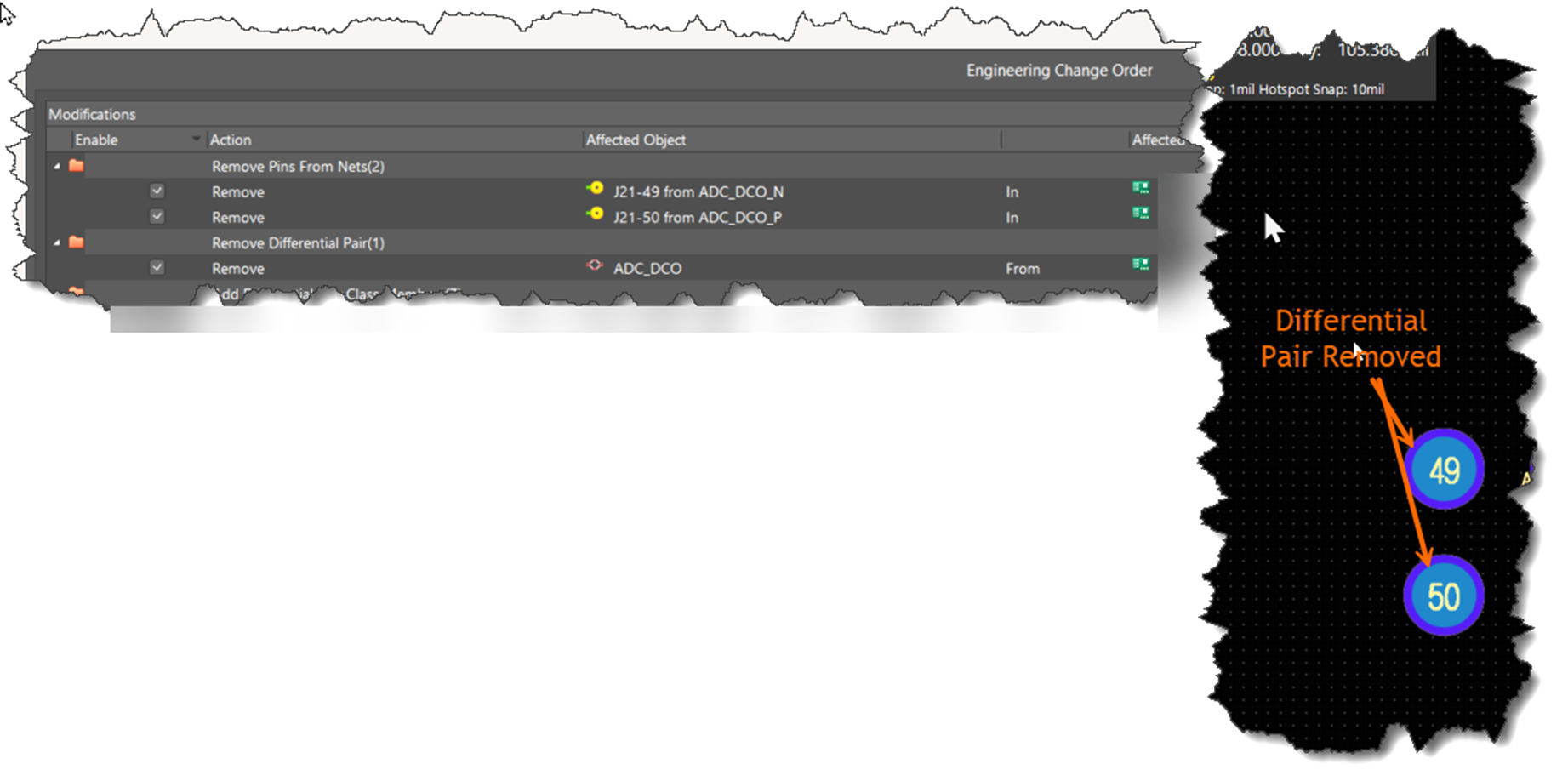
Update the PCB using the ECO process and and confirm that affected differential pairs have been deleted on the PCB - Recreate the differential pairs in the schematic using correct labels and directives.
- Update the PCB again using the ECO process.
- In the PCB Panel, verify both nets are assigned to each pair.
- Route the differential pairs — the error should be resolved.
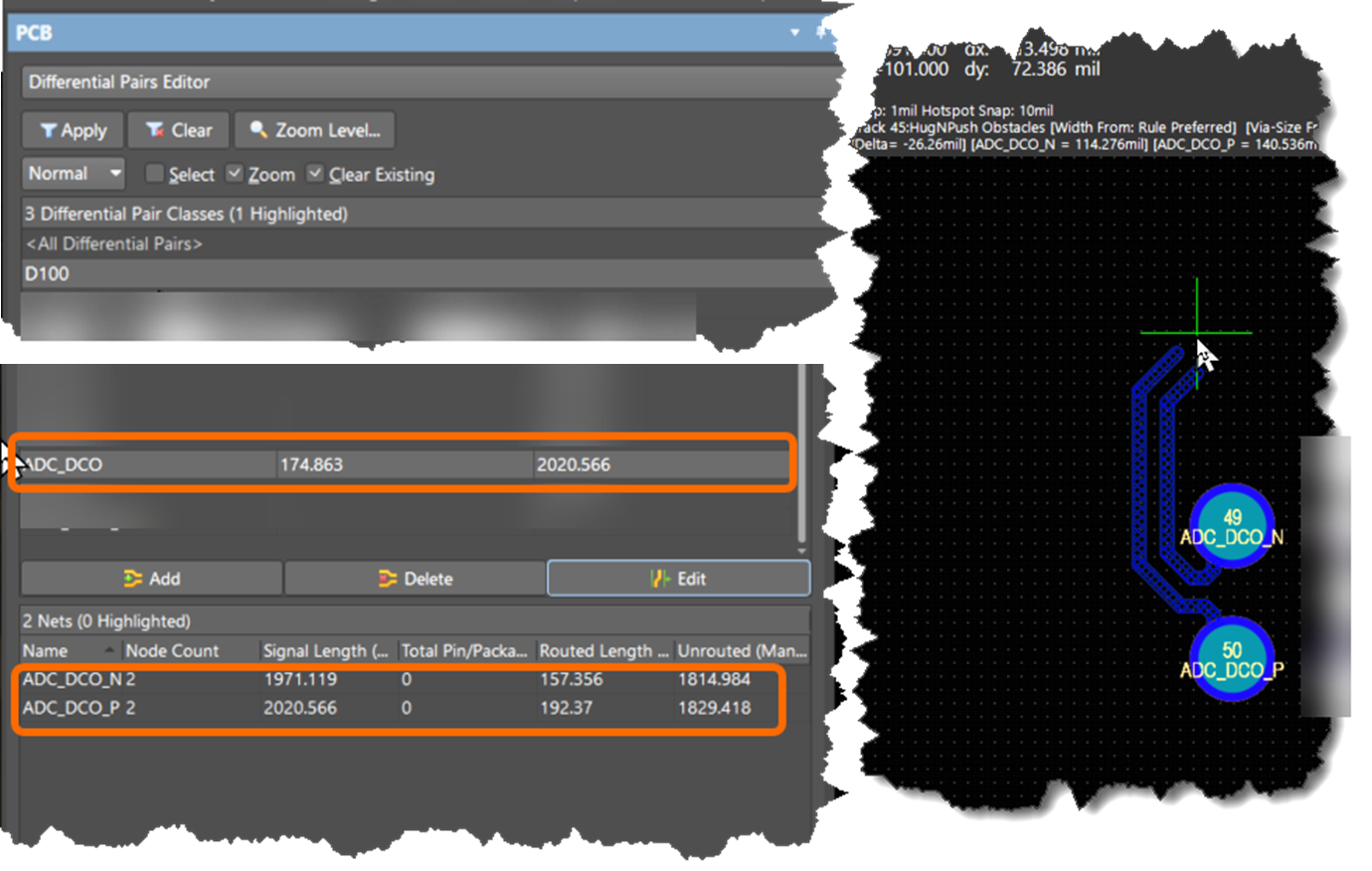
PCB panel with updated differential pair showing both nets of the differential pair. Routing the differential pair does not generate the error
Option 2: Manually Assign Nets in PCB Panel
- Open the PCB Panel: Panels » PCB
- Select Differential Pairs Editor from the dropdown.
- Locate and select the affected differential pairs
- Click Edit.
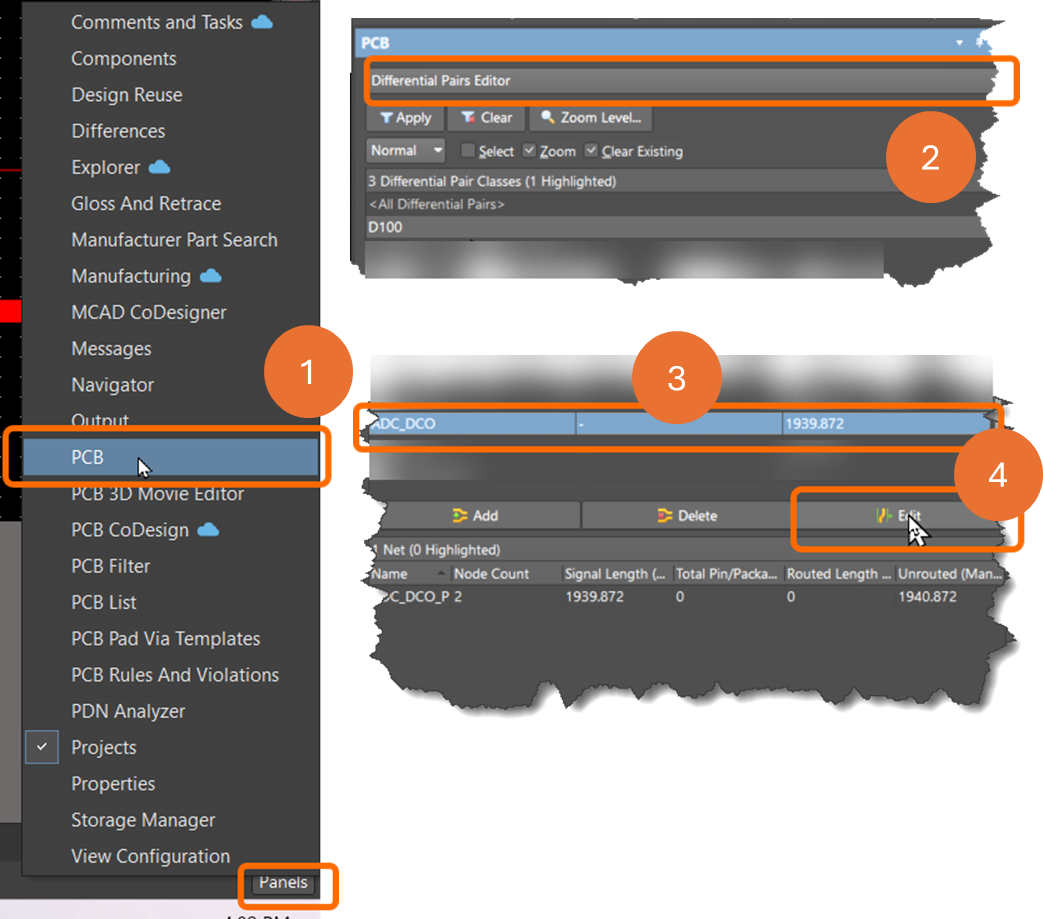
Editing the affected differential pair in the PCB panel - In the pop-up window, assign missing nets to the Positive and/or Negative fields.
- Confirm both nets are assigned in the PCB Panel.
- Route the differential pairs — the error should be resolved.
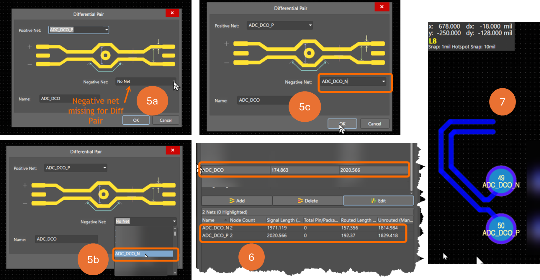 |
| Assign missing Positive and/or Negative nets to the affected differential pair , confirm that both nets are assigned in the PCB panel and route the differential pair. |
Additional Notes
- These workarounds resolve the routing error but do not address the underlying ECO update issue.
- Always verify net assignments in the Differential Pairs Editor after making changes.
- If ECO updates fail repeatedly, manually verifying and editing differential pair definitions in both the schematic and PCB is recommended. Altium’s synchronization tools may not resolve all issues automatically.