
KB: Automatic Trace Width Reduction in Connector Escape Areas
 Altium Designer
Solution Details
Narrow Connector Escape Area Requires Reduced Widths
A design requires traces to be routed beneath a 144-pin through-hole connector. The preferred routing width for the PCB is 8 mil, but only 6 mil traces can fit within the connector escape region. Manually reducing individual track segments is possible; however, this method is time-consuming, difficult to maintain, and does not ensure that all routing within the connector region consistently follows the required width constraints.
Width Rules Control Routing Behavior
Altium Designer applies routing widths according to the active Width Constraint Rules. Without a more specific rule, routing uses the widths defined by the applicable global or net-specific constraints. Although interactive routing can automatically neck down traces in certain situations, manually shrinking track segments does not create a persistent design rule and cannot guarantee consistent routing behavior throughout the design. By defining a dedicated routing region and assigning a specific Width Constraint Rule to that region, narrower routing widths can be applied automatically and consistently wherever required.
Use a Room-Specific Width Constraint Rule
Create a Room that covers the connector escape area and define a Width Constraint Rule that targets routing within that Room.
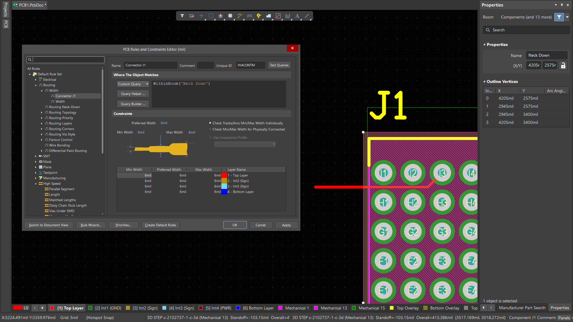
Use the following query in the rule scope: WithinRoom('Neck Down')
This allows Altium Designer to automatically apply a narrower width whenever routing occurs inside the defined region, while leaving routing outside the Room unaffected.
Configure And Apply The Routing Rule
- Open the PCB document.
- Place a Room over the area beneath the through-hole connector.
- Resize the Room to cover the intended routing region.
- Assign a meaningful Room name, for example:
Neck Down - Select Design » Rules.
- Navigate to Routing » Width.
- Create a new Width Constraint Rule.
- In the rule scope, enter:
WithinRoom('Neck Down') - Define the required routing widths for the Room.
- Ensure the Room-specific Width Rule has a higher priority than any broader Width Rules that may also apply to the same nets.
- Apply the rule and create new routing within the Room.
- If necessary, re-route or modify existing routing so the new Width Constraint Rule is reflected in the design.
- Verify that traces routed within the Room use the narrower width while routing outside the Room continues to use the standard board width.
- Select track segments inside the Room and review the applied width in the Properties panel.
- Run a Design Rule Check (DRC) if required.
Additional Notes
Using Room Query Functions
WithinRoom('Neck Down'): Targets routing objects located within the specified Room. This is typically the preferred option when creating a controlled neck-down region beneath a connector.TouchesRoom('Neck Down'): Targets objects that intersect or touch the Room boundary. This can be useful when routing behavior needs to be controlled at the transition into or out of the Room.
Relationship To The Routing Neck-Down Rule
This article focuses on using a Room and Width Constraint Rule to define where narrower routing widths should be applied. Altium Designer also includes a Routing Neck-Down rule, which serves a different purpose. The Routing Neck-Down rule can be used to define and validate the maximum permitted length of routing that is narrower than the preferred width defined by the applicable Width Constraint Rule.
In many designs, these features can be used together:
- A Room-based Width Constraint Rule defines the neck-down region beneath the connector.
- A Routing Neck-Down Rule validates that the total length of reduced-width routing remains within acceptable limits.
Design Considerations
- Use a Room-based Width Rule when routing width should change based on PCB location rather than net membership.
- Ensure the Room-specific Width Rule has a higher priority than broader routing width rules.
- Consider using WithinRoom() for most connector escape-routing applications.
- Use TouchesRoom() when routing behavior needs to be controlled at the Room boundary.
- If reduced-width routing must be limited for signal integrity or manufacturing reasons, consider using a Routing Neck-Down rule in addition to the Room-based Width Rule.