
Working with Rooms on a PCB
At a Glance
- You will learn what a room is on a PCB and how it is used to control object placement and design requirements within a defined board area.
- You will see the main methods for creating rooms in the PCB editor, including interactive placement, creation from selected components, and creation through design constraints.
- You will understand how room objects and Room Definition constraints work together in Altium Designer, including how this applies in the PCB Rules and Constraints Editor and the Constraint Manager.
Summary
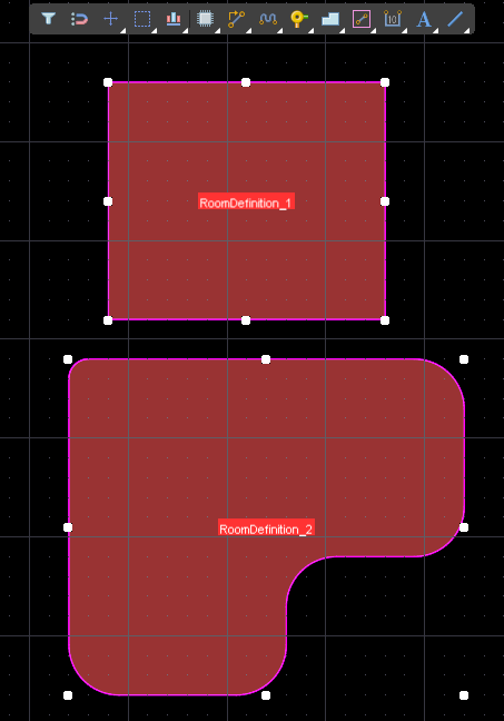 A room is a defined area on one of the PCB surface layers. A room is used to define design requirements within that area of the board, such as: these components must be in this area, or, route these nets this width, or, use routing vias of this size.
A room is placed like other polygonal objects, either as a rectangular shape, or as a polygonal shape.
As well as existing as a named X-Y shape on the board, each room automatically becomes a named Room Definition design constraint (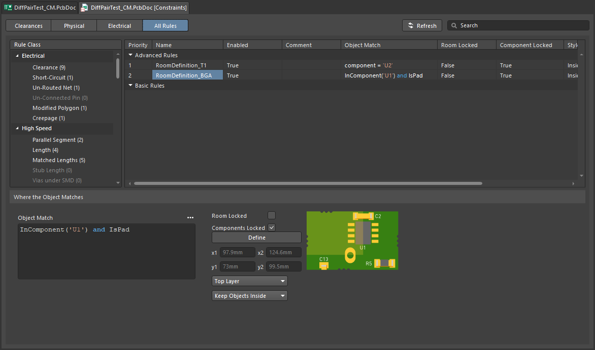 ). The settings in the Room Definition constraint define: the objects that the room applies to, if those objects are to be kept inside or outside of the room, and the layer the room is applied on.
Beyond the simple, keep these objects in (or out) requirement that the Room Definition constraint specifies directly, the room can also be used to define an area of the board where other design constraints are applied. For example, the routing under a BGA might need to be a specific width (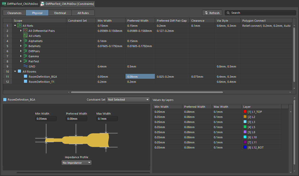 ), or, the differential pair routing under a BGA might require a specific impedance profile to be applied (
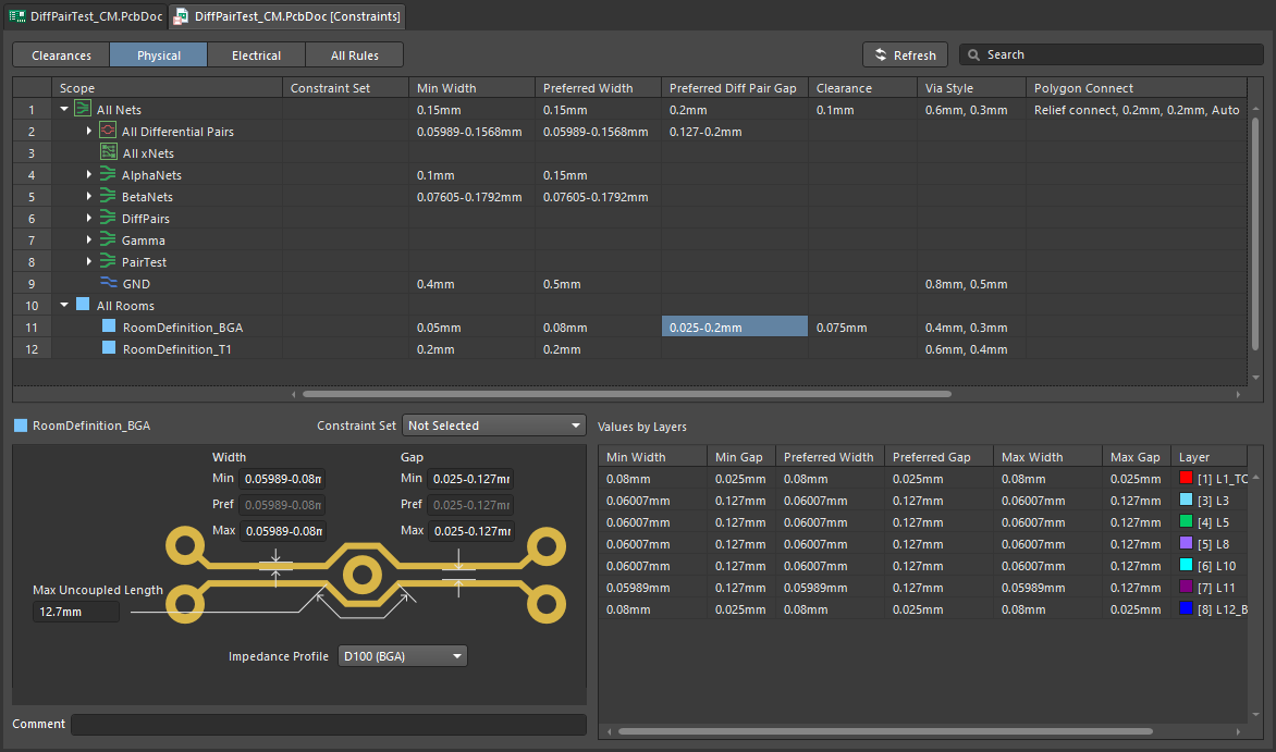 ).
).
Availability
Rooms are only available for placement/creation in the PCB Editor. Use the following methods to create rooms:
-
Select the required command from the Design » Rooms submenu, then either interactively define the room shape (if you selected a Place command), or automatically create the room (if you selected a Create command).
-
Add a new Room Definition design constraint, then edit the new room constraint, then click the Define button to interactively define the shape of the polygonal room.
-
Create a room based on a (selected) closed outline formed by a set of tracks / arcs, using the Tools » Convert » Create Room from Selected Primitives command.
-
Automatically create rooms during schematic to PCB design synchronization. Learn more about automatically generated rooms (including how to disable them).
Creating a Room
The procedure used to create a room on the PCB document depends on whether you are interactively placing or creating the room, and which particular method of placement/creation you have chosen to use.
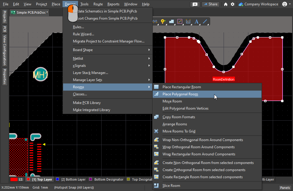 Different techniques are available to place or create a room.
Interactive Room Placement
Rectangular or polygonal-shaped rooms can be placed on the top or bottom layers of the design. Note that even though they can be placed when any layer is active, the layer they apply to is assigned as part of the Room Definition design constraint.
Rectangular Room
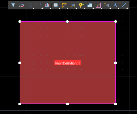
After launching the Design » Rooms » Place Rectangular Room command, the cursor will change to a crosshair, and you will enter room placement mode. Placement is made by performing the following sequence of actions:
-
Click or press Enter to anchor the first corner of the room.
-
To edit the properties of the associated Room Definition constraint on-the-fly, press the Tab key during placement.
-
Move the cursor to adjust the size of the room then click or press Enter to anchor the diagonally opposite corner and complete placement of the room.
-
Continue placing further rooms or right-click or press Esc to exit placement mode.
Polygonal Room
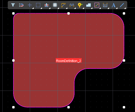
After launching the Design » Rooms » Place Polygonal Room command, the cursor will change to a crosshair and you will enter room placement mode. Placement is made by performing the following sequence of actions:
-
Position the cursor then click to anchor the starting point for the room.
-
Position the cursor then click to anchor a series of vertex points that define the polygonal shape of the room.
-
After placing the final vertex point, right-click or press Esc to complete placement of the room. There is no need to close the polygon since the software will automatically complete the shape by connecting the start point to the final point placed.
-
Continue placing further polygonal rooms or right-click or press Esc to exit placement mode.
Based on Selected Components
If the components are already positioned on the board and you want to create a new room to suit their placement, use one of the three Create xxx Room from selected components commands. Non-orthogonal, orthogonal, and rectangular-shaped rooms can be created automatically using one of these commands, based on the components currently selected in the design space. In each case, the method of creation is the same:
-
Select all of components for which you want to create the room. To select the PCB components from the schematic, run the Tools » Cross Select Mode command then select the components on the schematic.
-
In the PCB editor, launch the relevant creation command (Design » Rooms » Create xxx Room from selected components). A component class will be automatically created that includes the selected components (unless one already exists).
-
The chosen room type is then created, with that room's Room Definition design rule automatically associated with the created component class.
-
The room will be sized accordingly to fit all of the components in the selection, based on the components' selection rectangles.
-
If you click and drag to move that room, all of the components in the associated component class will also move.
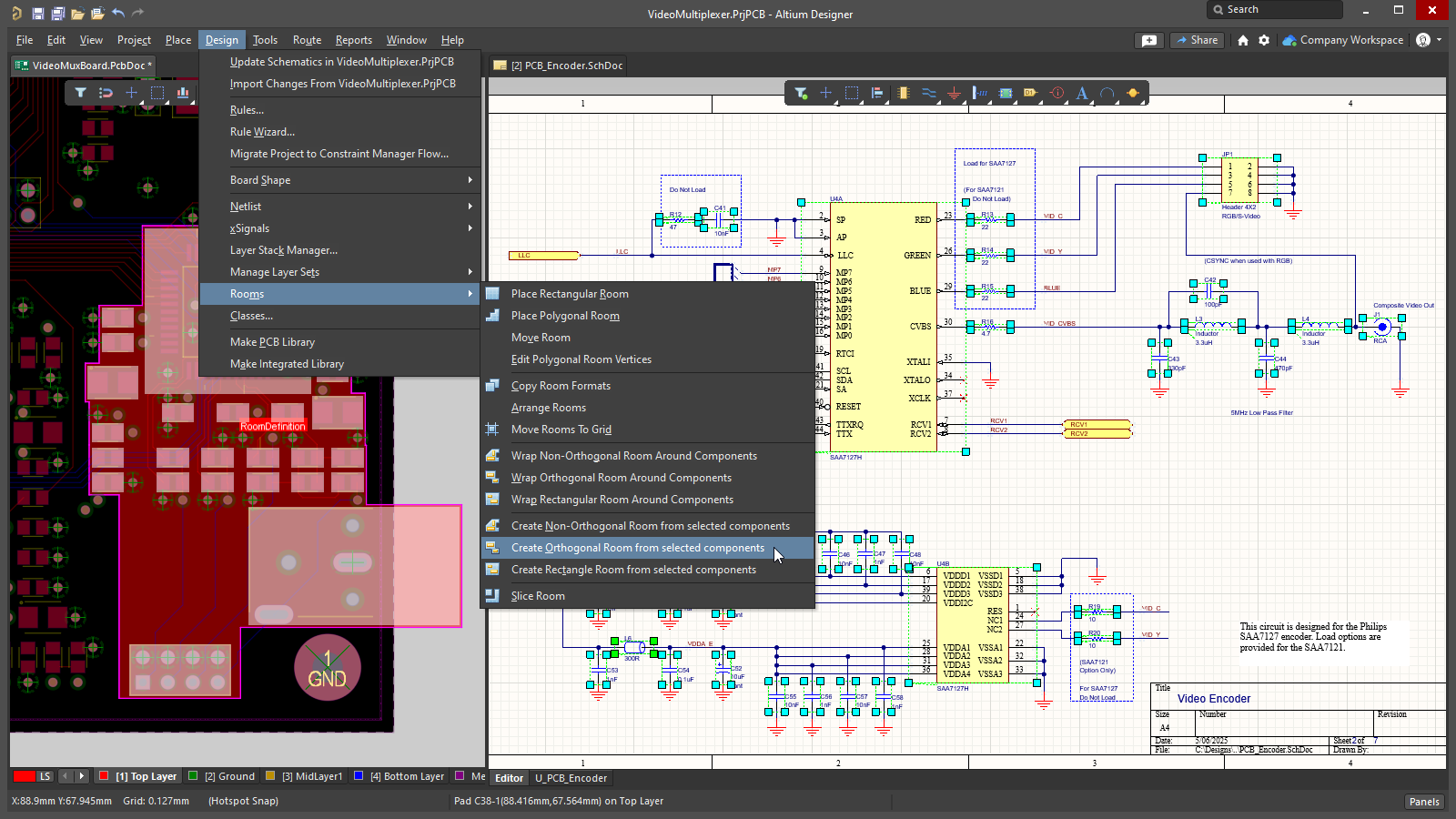 An orthogonal room is created from the selected PCB components, which were selected from the schematic.
By Adding a Room Definition Design Constraint
A new room can also be created by defining a new constraint in the PCB Rule and Constraints Editor or the Constraint Manager.
Which approach is being used to Define the Design Constraints?
Altium Designer supports two distinct approaches to defining design constraints: the Constraint Manager and the PCB Rule and Constraints Editor.
The PCB Rule and Constraints Editor was the initial interface developed for defining constraints in the PCB editor. If the PCB Rule and Constraints Editor is used, the designer defines: what objects the constraint (rule) applies to, and, how those objects are to be constrained. This approach is powerful in that it allows the designer to precisely target the objects they want to constrain; it could apply to everything (for example all nets), or zoom right in to a specific object on the board (that pad). This flexible method of targeting the design objects is achieved using a rules engine driven by a query language.
The Constraint Manager brings an object-centric focus to the task of defining the constraints. The designer works from the perspective of the objects, applying the various electrical and physical constraints required for the design, in a spreadsheet-like interface, with the object(s) highlighting in the graphical editor as they are selected in the Constraint Manager. This allows the designer to easily configure and examine all of the requirements for an object, for example: this net class, is to be routed at this width, with this clearance, using this routing via, and this polygon connection style. You might also require that net class to be: routed on these layers, with these impedances. This object-centric view is not possible in the PCB Rule and Constraints Editor. Ultimately the software converts the object-centric constraints into the same format of rules that is defined in the PCB Rule and Constraints Editor, switch to the All Rules view when the constraints have been opened from the PCB editor to view them.
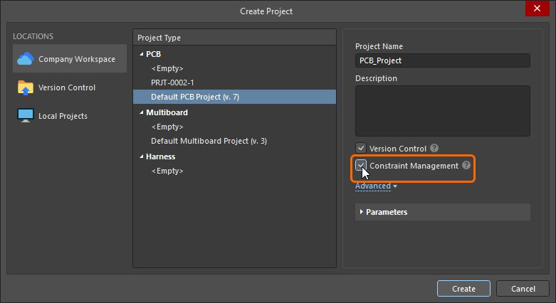 ).
).This documentation page shows images of the constraints as they are defined in both the PCB Rule and Constraints Editor dialog and the Constraint Manager. Note that the terms constraint and rule are used interchangeably.
Adding a New Room Definition Design Constraint
In the PCB Rules and Constraints Editor
For each room that is placed or created, an associated Room Definition design constraint is automatically created. The converse is true too, if you add a new rule of this type, the corresponding room object will appear in the design space. Note that the opposite also applies, if you delete a room in the graphical editor the constraint is automatically deleted, or, if you delete the design constraint then the graphical object is deleted.
If the room constraint is being defined from the PCB Rules and Constraint Editor, then a default 5-inch by 5-inch room object is created, 1 inch from the Absolute Origin (the bottom left of the editing space). Note that the origin marker displays the user-defined Relative Origin, which can be set anywhere in the editing space.
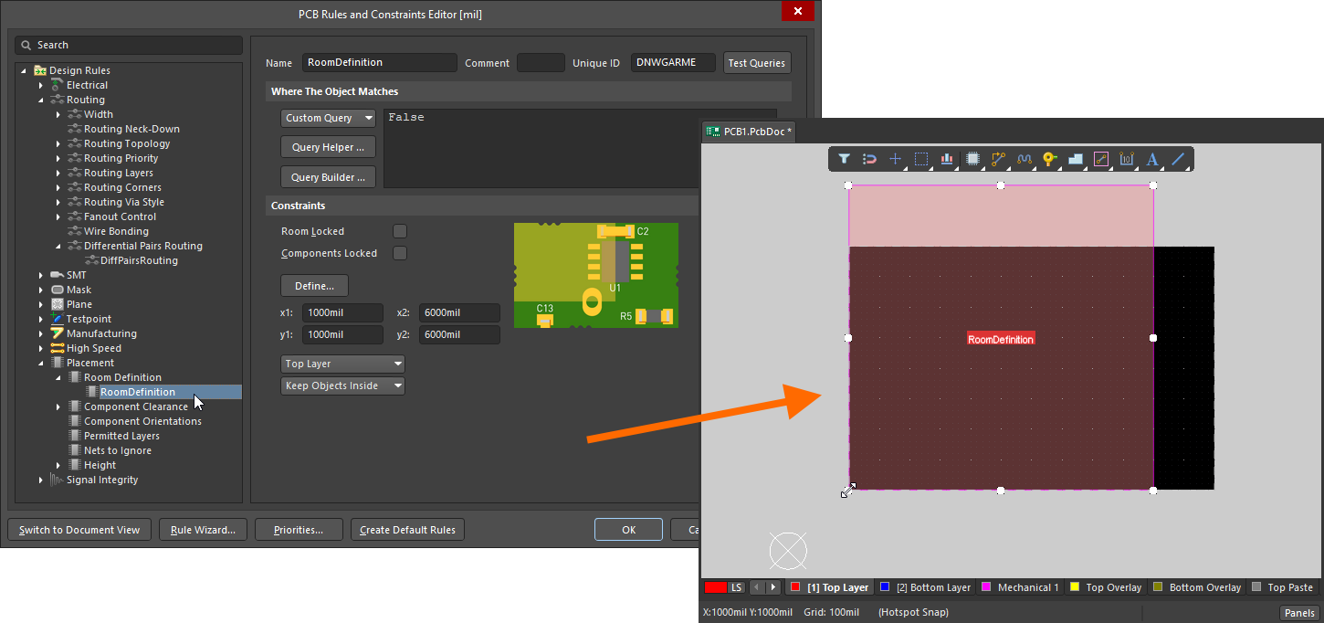 When a new room constraint is added, a default room is defined in the editing space.
Once the constraint has been added you can return to the editing space and graphically edit the room. Alternatively, when you are in the PCB Rules and Constraints Editor you can edit the room constraint, then click the Define button to interactively define the shape. Since a room defines an area on the board, it is more common to interactively place the room and have the design constraint automatically created.
Learn more about how to add a new constraint in the PCB Rules and Constraints Editor.
In the Constraint Manager
To create a new confinement (room) constraint in the Constraint Manager: switch to the All Rules view, select Room Definition in the Placement category, then right-click in the Advanced Rules list and select Add Advanced Rule from the context menu, as shown below.
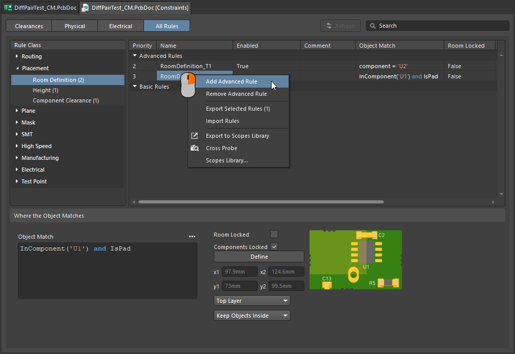 A new room constraint can be added in the Constraint Manager.
At this stage the room object does not exist in the graphical editing space, you must now click the Define button (switching you to the PCB editor) and define the shape of the room. Once this has been done, both the room constraint and the room object exist, and the constraints can be saved.
-
If the room constraint is going to be used to constrain objects to be inside (or outside) that area of the board, the next step is to configure the Object Match and other constraint settings at the bottom of the Constraint Manager. Read on to learn more about that.
-
If the room constraint is going to be used as an area definition in another type of constraint, such as the routing width, refer to the Defining Constraints Within a Room section to learn more.
Learn more about how to add a new constraint in the Constraints Manager.
What is a Room Constraint?
As stated earlier, a room is a defined area on one of the PCB surface layers, that is used to define design requirements within that area of the board.
All design constraints have two key elements:
-
what objects this constraint applies to (
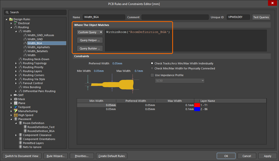 ), and,
-
how those objects are to be constrained (
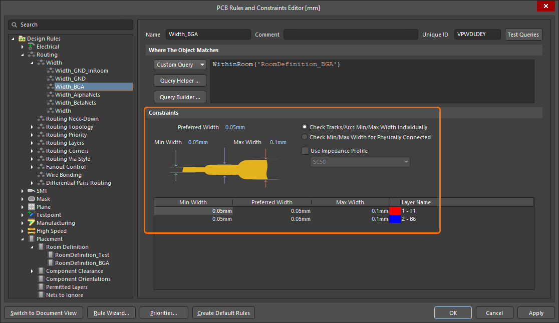 ).
).
If the room constraint is defined in an area of the board where there are no components, the Object Match criteria (the objects this constraint applies to) defaults to False, meaning this constraint applies to no objects. Edit this as required.
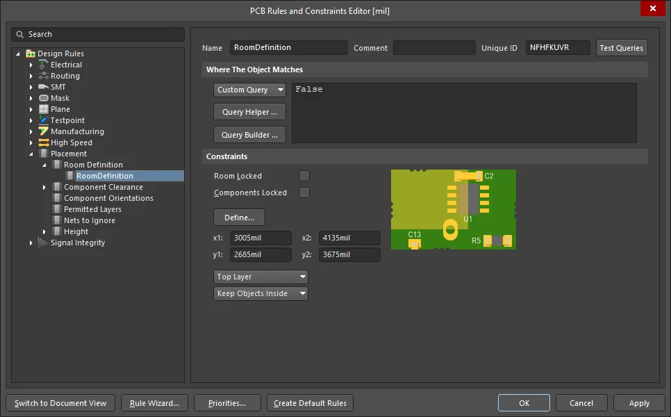 The newly created room definition. Note that the rule scope is False, meaning it applies to no objects.
Constraining a Class of Components
A common way to use a room constraint is to define the location of a component class, locking that class of components to a specific area of the board.
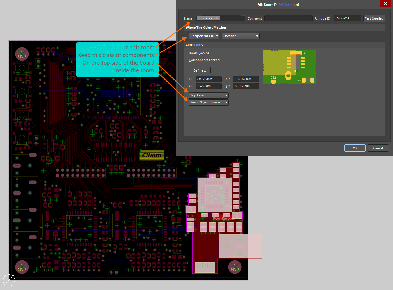 The Encoder class of components is constrained within the room called Room-Encoder, on the Top Layer of the board.
The image above shows how the Encoder class of components is constrained within the Room-Encoder room, on the Top side of the board in the PCB Rules and Constraints Editor (essentially the same as in the Constraint Manager 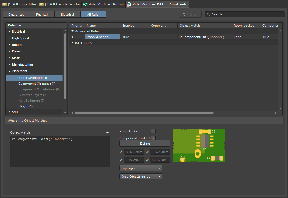 ). Once component(s) have been assigned to a room, they move when the room is moved. To move a room without moving the components, temporarily disable the associated Room Definition rule.
Learn more about the Room Definition design constraint.
The PCB editor includes a number of powerful tools for working with rooms, read more in the Working with Rooms section of this page.
As well as being a design constraint in its own right (Room Definition), a room can also be used as an object to focus the scope of another design constraint to an area of the board, such as Width, Clearance or Via Style. This topic is discussed in the the Defining Constraints Within a Room section of this page.
Created During Schematic to PCB Design Synchronization
As the design is transferred from the schematic to the PCB, you have the option to create a room containing the components on each schematic sheet. In a multi-level hierarchical design this may be of little value, but in a large flat design, having a room for each sheet can be helpful when it comes to positioning the components on the board.
The Class Generation tab of the Project Options dialog includes options to generate rooms for each sheet in the design (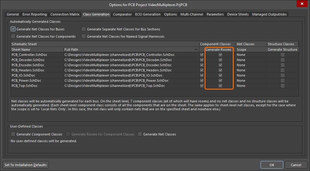 ). If the Generate Rooms option is checked, a room will be created for that sheet and a class of all the components within that sheet will be assigned to that room when the Design » Update command is run. Note that the components in each sheet are added to a component class, so the Generate Rooms option requires the corresponding Component Class option to also be enabled.
In the PCB, each room constraint is created with the scope of InComponentClass('<SheetSymbolDesignator>'). A room will not be created if the sheet does not contain any components. When the schematic is initially transferred to the PCB, the components in each component class are arranged in a row, and then a room is created around that component class, as shown in the image below.
Disable the Generate Rooms checkboxes in the Project Options dialog if automatically generated rooms are not required.
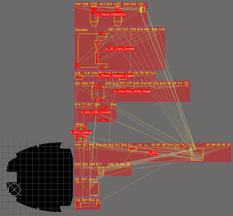 The PCB after initial design synchronization - a room has been created for each sheet, with that sheet's component class assigned to it.
Learn more about automatically generating Rooms, Component Classes and Net Classes from the schematic project.
To learn more about design synchronization, refer to the Keeping the Schematics & PCB Synchronized page.
From Selected Tracks and Arcs
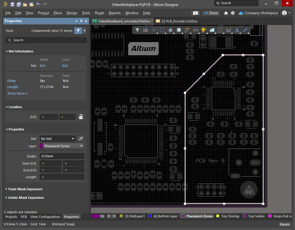
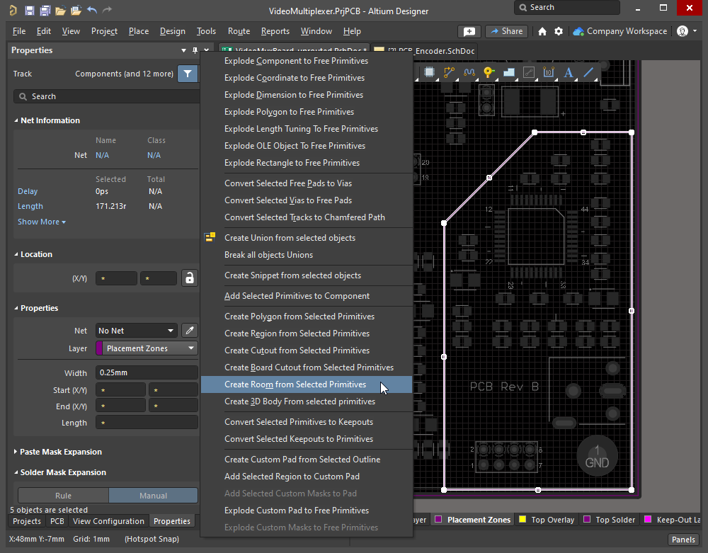
A room object can be defined using a closed boundary made up of selected track and/or arc objects. To do this, select all constituent track and arc primitives of the closed boundary in the design space and choose the Tools » Convert » Create Room from Selected Primitives command from the main menus. The slideshow below demonstrates the steps involved.
|
Tracks have been placed on a mechanical layer to define the board space available for the Encoder components. Run the Tools » Convert » Create Room from Selected Primitives command to create a Room Definition of the same shape. The Edit Room Definition dialog appears so that the parameters of the constraint can be defined. The To adjust the shape of the room, click to select it, then run the Design » Rooms » Edit Polygonal Verticies command, and click on a vertex or an edge to re-shape the room. |
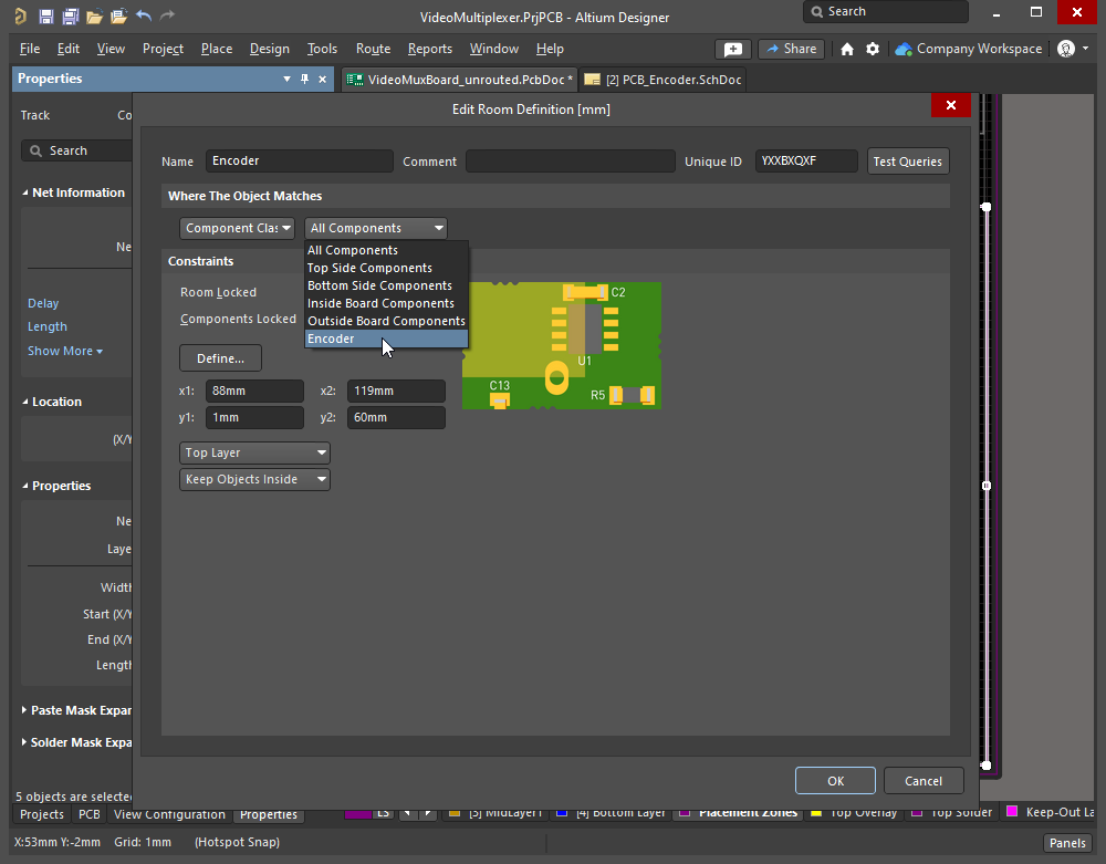
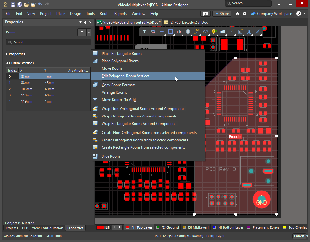
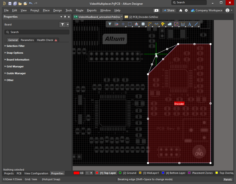
Editing a Room
The X-Y shape of the room and its location on the board can be modified interactively. Note that there are two different processes used to interactively edit a room, either: based on its selection rectangle (described in the Changing the Size and Location section), or based on its shape editing vertices (described in the Changing the Shape section).
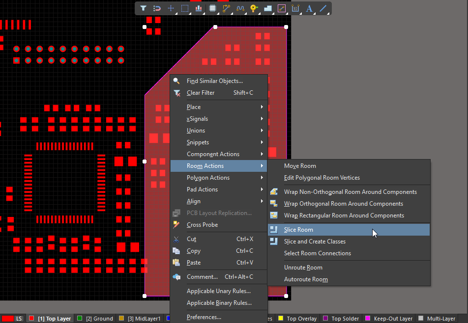
As well as accessing the commands using the Design » Rooms sub-menu, you can also access context-specific room commands by right-clicking on a placed room and selecting the Room Actions sub-menu.
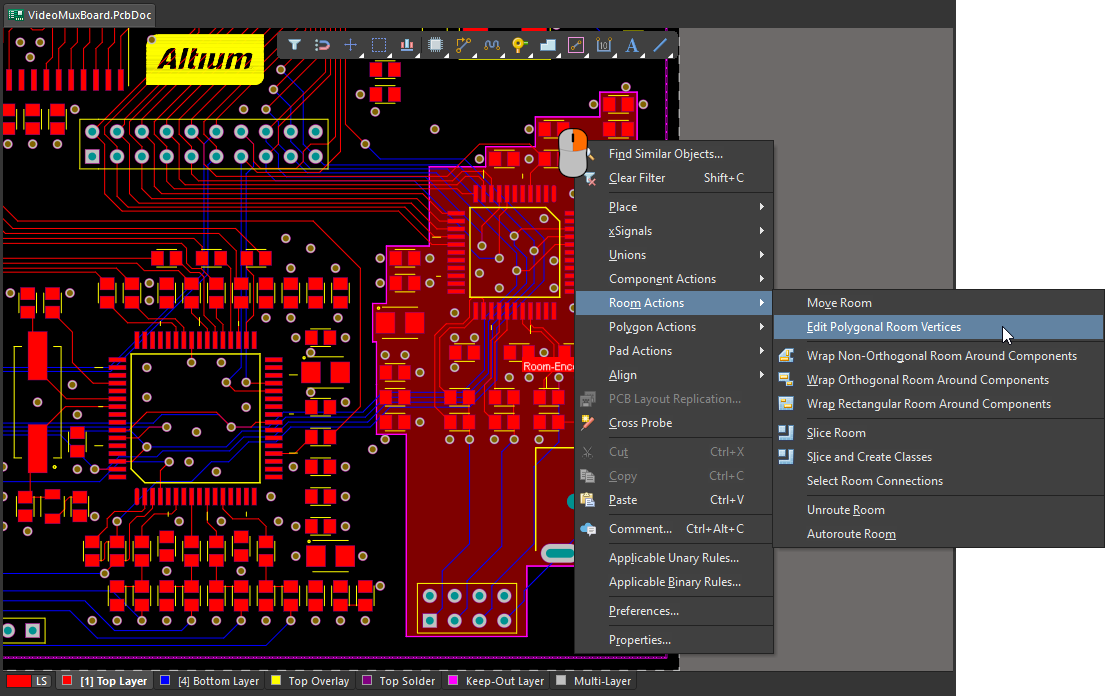 Right-click on a room to access room-specific commands.
Changing the Size and Location
When you click once on a room to select it, the following editing handles become available – regardless of whether the room was originally placed as a rectangular or polygonal room:
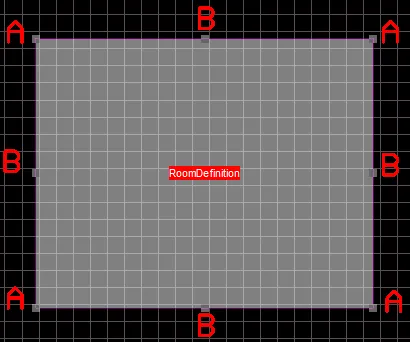
 Editing handles appear when you click to select a room.
Changing the Size of the Room
-
Dragging corner handles (A) will scale the room horizontally and vertically simultaneously.
-
Dragging an edge handle (B) scales the object in that direction (either horizontally or vertically).
-
The room can be rotated or flipped while dragging by pressing the:
-
Spacebar to rotate the object counterclockwise or Shift+Spacebar for clockwise rotation. Rotation is in accordance with the value for the Rotation Step defined on the PCB Editor - General page of the Preferences dialog.
-
X or Y keys to flip the object along the X-axis or Y-axis.
-
L key to flip the object to the other side of the board. If the room has associated components, those components will be flipped along with the room.
-
Moving a Room
Click and drag on a room to move it to a new location. A room object can also be moved using the Design » Rooms » Move Room command from the main menus or the Room Actions » Move Room command from the room's context menu. After launching the command, the cursor will change to a cross-hair and you will enter room movement mode – click on the room to move it.
When you click on a room to move it:
-
The room will attach to the cursor. The point that the room is held by depends on the current Object Snap Options (
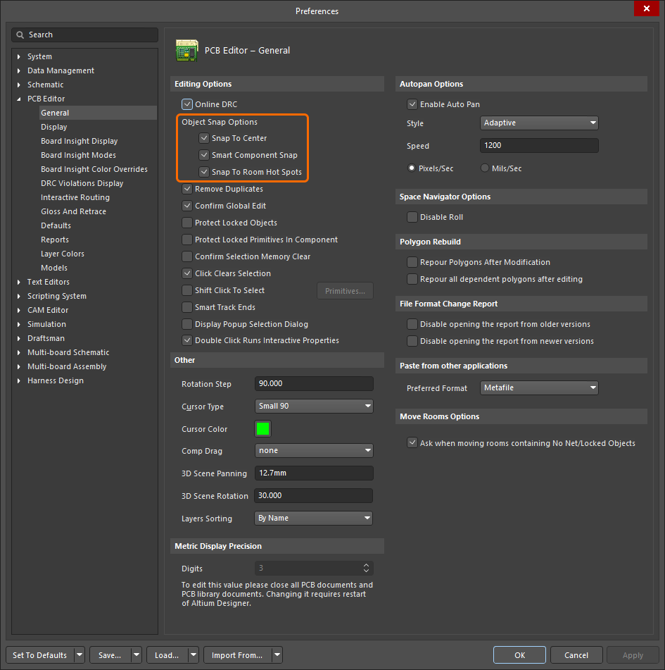 ), with the cursor snapping to the nearest of the enabled snap points (component pad, component reference, or room vertex).
-
Move the room to the required position then click or press Enter to effect placement.
-
Continue moving further rooms or right-click or press Esc to exit.
-
If there are components in the room being moved, green dynamic alignment guides can be displayed during movement by pressing the Shift or Ctrl keys. Use Shift to keep snapping to the active grid, use Ctrl to temporarily inhibit the grid and align to an existing off-grid object.
-
If the room contains any no-net objects and/or locked objects, the Room containing No Net/Locked Objects dialog will open. Use this dialog to determine whether these objects should be moved with the room or not then click OK. For this dialog to appear, the Ask when moving rooms containing No Net/Locked Objects option must be enabled on the PCB Editor - General page of the Preferences dialog (
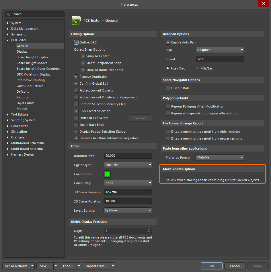 ).
).
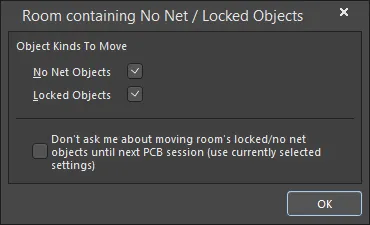
The Room containing No Net / Locked Objects dialog
Room containing No Net / Locked Objects dialog |
|
| No Net Objects | Enable to move objects with no nets with the room. |
| Locked Objects | Enable to move locked objects with the room. |
| Don't ask me about moving room's locked/no net objects until next PCB session (use currently selected settings) | Enable this option to save the selected settings and continue using them for the rest of your PCB session. The dialog will not open again until a new session is started. |
Changing the Shape
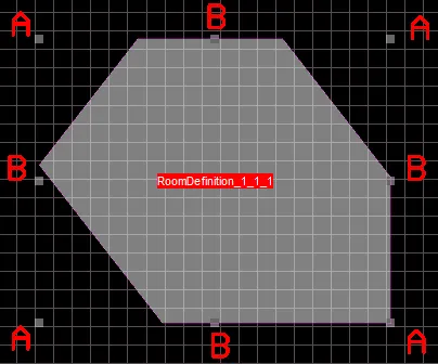
The boundary shape of a room is modified by running the Edit Polygonal Room Vertices command. The command is accessed via the Design » Rooms sub-menu, or the right-click Room Actions context sub-menu.
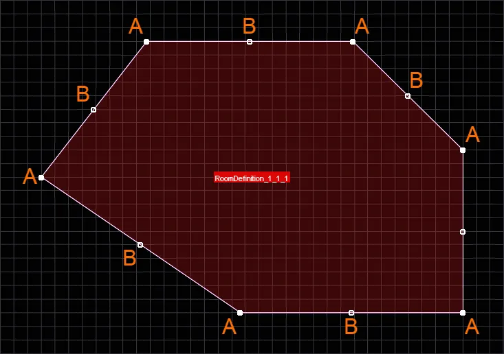
When you run the command the boundary editing handles for the room's polygonal shape are displayed, you can then:
-
Click an A handle, then move the cursor to move that vertex. Click again at the new location to position the vertex.
-
While moving an A handle, press the Delete key on the keyboard to remove that vertex from the room.
-
Click B or click along an edge (in between handles), then move the cursor to slide that edge. Press Shift+Spacebar while moving the edge to cycle through the available edge behavior modes (sliding edge, breaking edge, incurvating edge).
-
Ctrl+Click B or Ctrl+Click along an edge, then move the cursor to add a vertex to that edge as well as move the vertex. Click again at the new location to position the vertex. In effect, the new vertex becomes an A vertex, and new B vertices are added between it and the original A vertices.
-
To access an off-grid handle, hold the Ctrl key down to temporarily inhibit grid snapping.
-
Continue modifying the shape of the room as required, or right-click or press Esc to stop. The display of the room will update in accordance with the new boundary shape.
This command can be used regardless of whether or not the target room is locked.
Slicing a Room
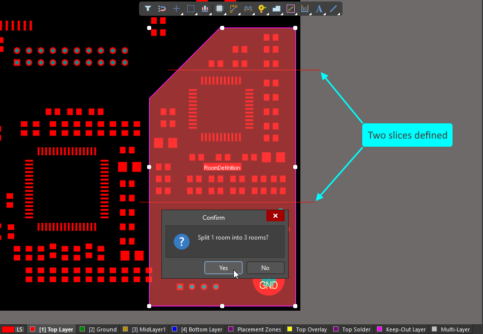
Commands are available to graphically slice a placed room object into two or more separate rooms. The slicing process is similar to placing a line and includes the same corner modes, (in fact the width of the slicing object is the current default line width). Note that the objects used to display the slice path are not objects being placed, they are only shown to display the slice path and are removed once the slicing process is complete. Also, there is no need to start slicing exactly on the edge of a room, it is easier to start slightly outside of the room, and to also finish slightly outside the room.
There are two slice commands available. The process of defining the slice path is the same for both, they differ in how they handle the components that are present in the room being sliced. The differences between the commands are explained after the slicing process is described.
|
Right-click on a room to access the Slice commands in the Room Actions menu. Two slices were defined, using the process described below. Three rooms have been created. |
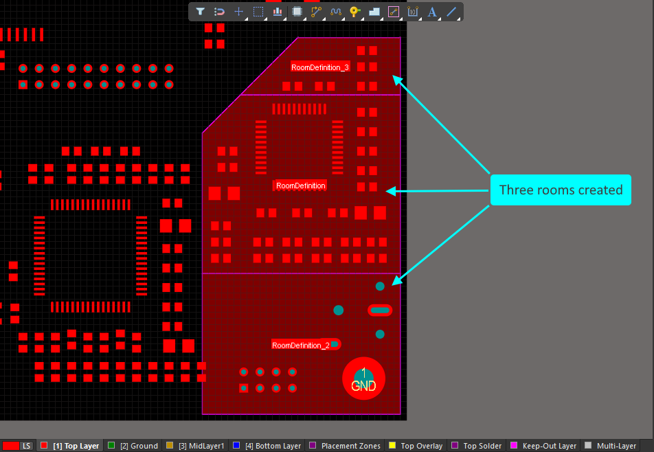
The Slicing Process
After launching a Slice command:
-
The cursor changes to a crosshair, and you are prompted to select a start point for the slice.
-
Position the cursor just outside the room you want to slice then click or press Enter. You are now in slice mode (essentially line placement mode).
-
Move the cursor into the room to define the first slice edge, then click or press Enter to anchor the end of that edge.
-
Continue to move the cursor and click, defining a series of vertex points that define the shape of the slice.
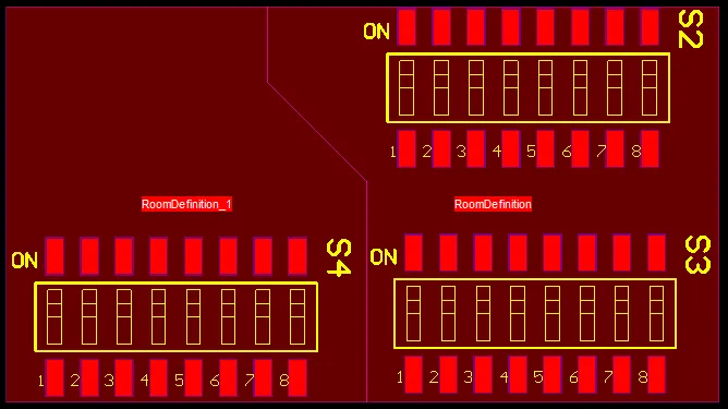
-
After placing the final vertex point (just outside of the room), right-click or press Esc to complete placement of that slice.
-
You can now either start another slice of the room, or right-click or press Esc to exit slice mode.
-
A confirmation dialog will open, which states how many rooms the original room will divided into. Click Yes to commit the slice(s) you have made, or No to discard. The resulting new room object(s) will be updated accordingly and the relevant Room Definition rule(s) created and associated.
-
During slicing, press:
-
Shift+Spacebar to cycle through the corner modes.
-
Spacebar to toggle the direction of the corner.
-
Each slice edge requires a start and end point.
-
If the slice placement mode includes a corner, press the 1 shortcut to toggle between placing one edge per click, or two edges per click.
-
Backspace to remove the last placed slice edge.
-
Re-Wrapping an Existing Room
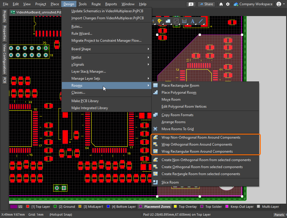
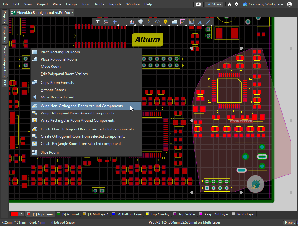
Another approach to modifying the shape of an existing room is to instruct the software to re-wrap the room around the component class assigned to that room. The right-click Room Actions sub-menu and the Design » Rooms sub-menu both include the three Wrap Room commands, as shown in the slideshow.
|
If you change the component placement within a room, use one of the three Wrap commands to update the room shape. The Wrap Non-Orthogonal command places room edges to join the extremities of the component boundaries. The Wrap Orthogonal command places vertical and horizontal room edges around the component boundaries. The Wrap Rectangular command places the smallest rectangular room that encloses the component boundaries. |
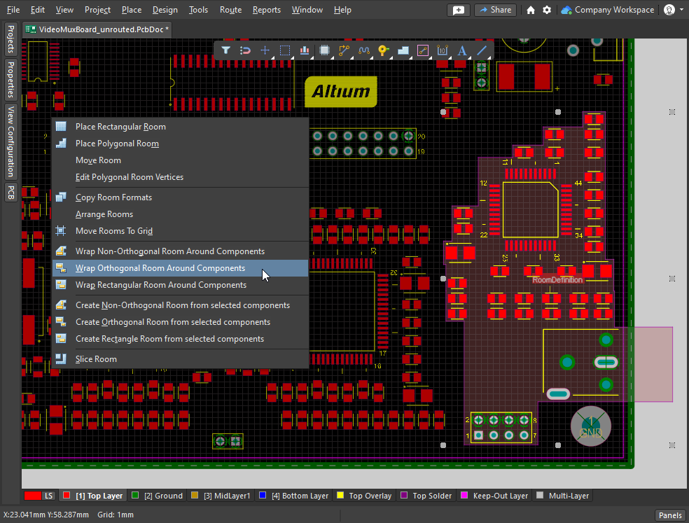
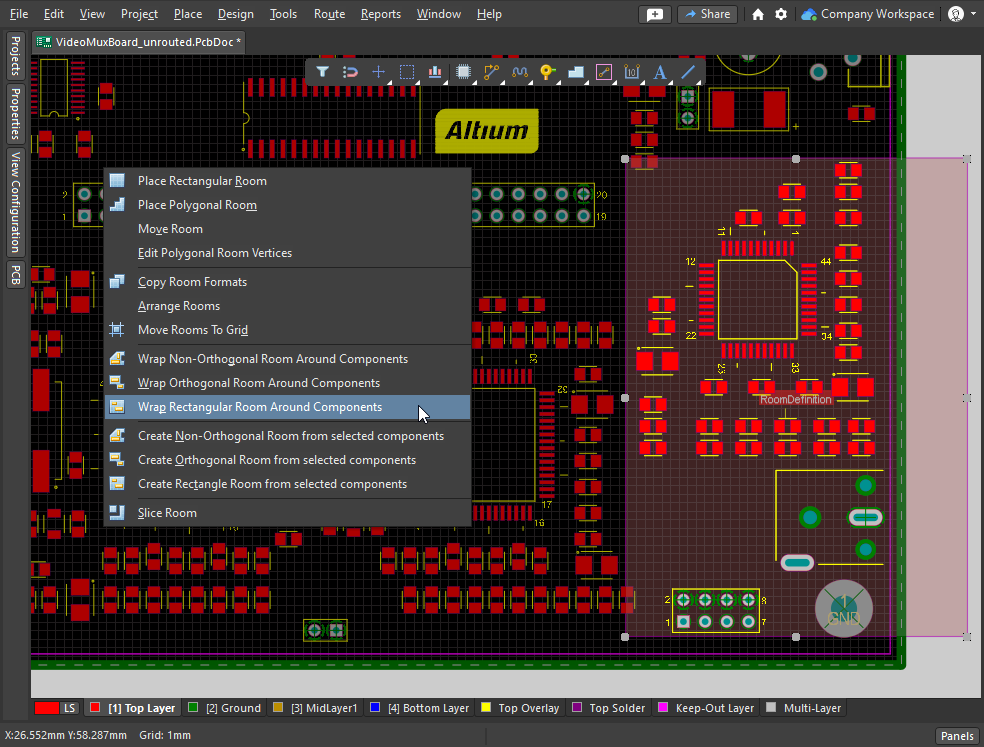
Editing in the Properties Panel
The room object is unusual in that it is both an object and a design constraint.
Editing via the Properties Panel
The properties of the room object, including the location and shape in the editing space, can be edited in the Properties panel when the room is selected. The panel can be displayed via the Panels the Panels button at the bottom right of the design space, or the View » Panels » Properties command.
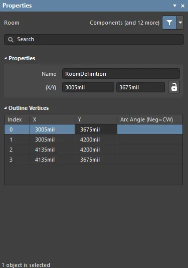 The Properties panel can be used to edit the graphical properties of a room.
| Name | The current name of the room (and the associated Room Definition rule). This can be changed as required. As well as helping identify each room, the name can be used to target a specific room in a design rule. |
| (X/Y) (two fields) | The current X and Y position of the first vertex of the room, relative to the current origin. Edit the value in the field to change the position of the room relative to the current origin. The value can be entered in either metric or imperial; include the units when entering a value whose units are not the current default. Default units (metric or imperial) are displayed on the Status bar and set in the Other region of the Properties panel (when there are no objects selected in the design space). These values can only be edited if the X/Y option is unlocked ( |
Outline Vertices |
|
| Vertices Grid | Lists all of the vertex points currently defined for the room, in the order they were defined as the room was placed. Straight line edges are used to connect one vertex point to the next. If you would rather have an arc connection, enter a value for the required Arc Angle. Entry is made in the field associated to the source vertex point with the arc being from this vertex to the subsequent vertex below in the list. Right-click to Copy / Paste or Import / Export to CSV. |
| Index | The assigned index of the vertex (non-editable, based on the order they were placed during room definition). |
| X | The X (horizontal) coordinate for the vertex. Click to edit. |
| Y | The Y (vertical) coordinate for the vertex. Click to edit. |
| Arc Angle (Neg = CW) | The angle of an arc that is drawn to connect this vertex point to the next. By default, connections are straight line edges with this field remaining blank. Click to edit then enter an arc angle as required. Entry of a positive value will result in an arc drawn counterclockwise. To draw a clockwise arc, enter a negative value. |
 icon is displayed).
Working with Rooms
The software includes a number of features to help you work with rooms, and the objects within them. This includes commands to: arrange the rooms in a grid pattern; move the rooms to the current snap grid; and for a design that includes repeated sections of circuitry, copy the placement and routing from one room to another.
You can also use a room to restrict other design constraints to an area of the board, requiring for example that in this room nets must be routed with a specific width and clearance, or differential pairs must be routed with a specific impedance profile.
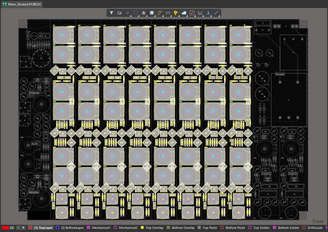 An 8-channel mixer, the first input channel was placed and routed, which was then replicated across the other seven input channels using the Copy Room Format command.
Defining Constraints Within a Room
As well as constraining objects to be inside or outside of a room (as discussed in the Room Definition Design Constraint section), a room can also be used as an area restriction in other design constraints. For example, the routing width constraint might require the routing under a BGA to be created with different widths, or the electrical clearance constraint might require different clearances in a specific area of the board.
The routing width and clearances are automatically adjusted within the room, in accordance with the settings in the Room Definition.
This is achieved by adding the Routing Width constraint and Electrical Clearance constraint shown in the slideshow below.
In the Constraint Manager
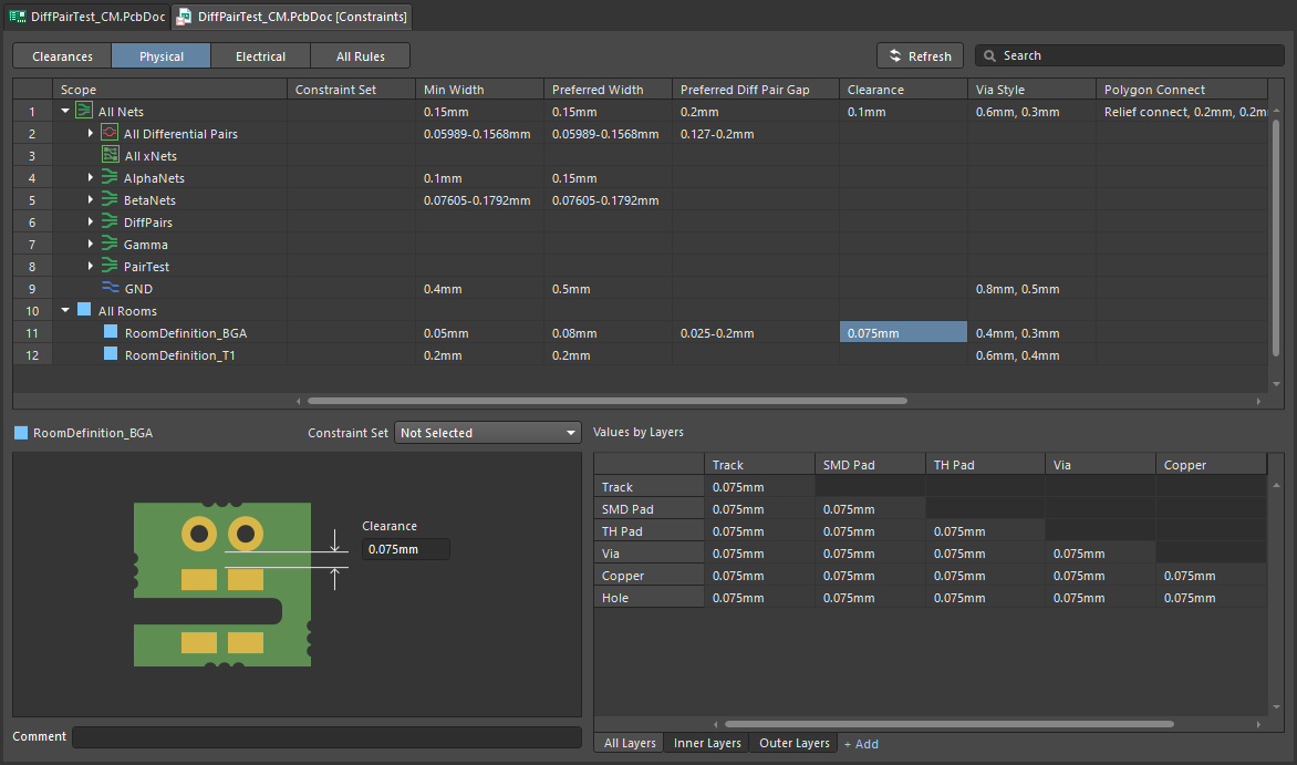
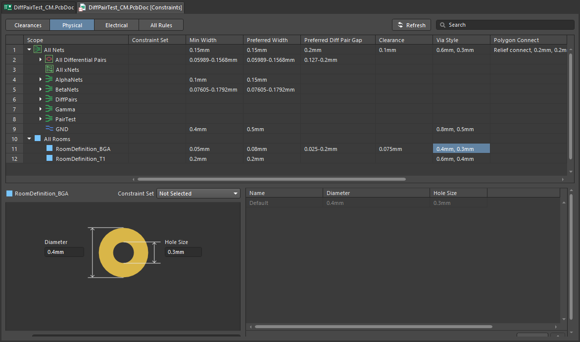
When a room constraint is added in the All Rules view in the Constraint Manager, that room object also becomes available in the Physical view. Using this view you can quickly define area-based constraints that must be applied within the room, including: the routing width, electrical clearance, routing via style, differential pair properties, routing neck-down and the polygon connection style. The slideshow below shows the constraints for the board in the video above.
|
Within this room, all routing objects must have a width within the specified range. Within this room, all routing objects must have at least this much clearance from objects belonging to other nets. Within this room, all routing objects must have at least this much electrical clearance. Within this room, all Differential Pairs must be routed using the |
In the PCB Rules and Constraint Editor
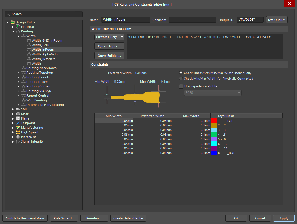
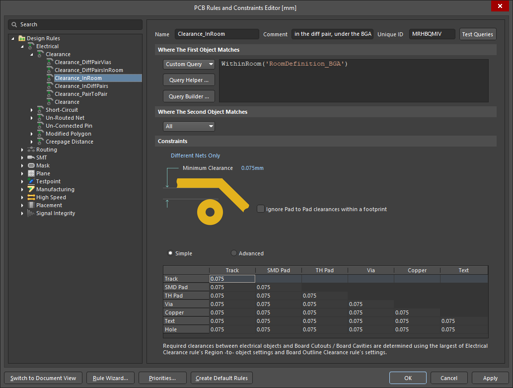
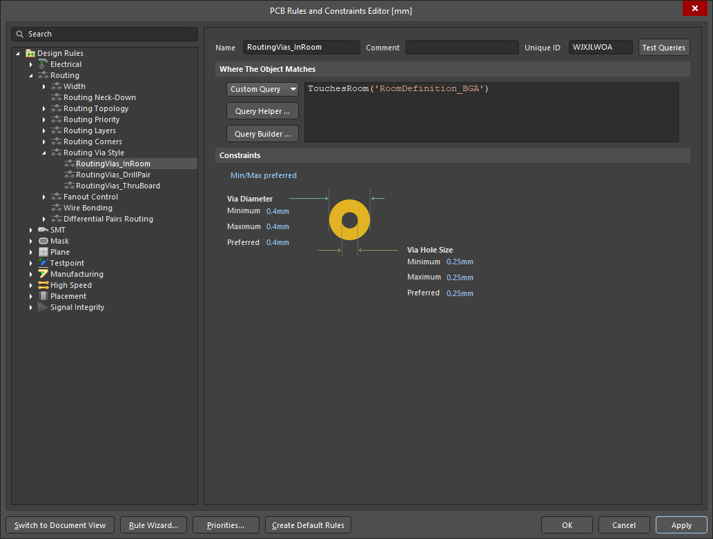
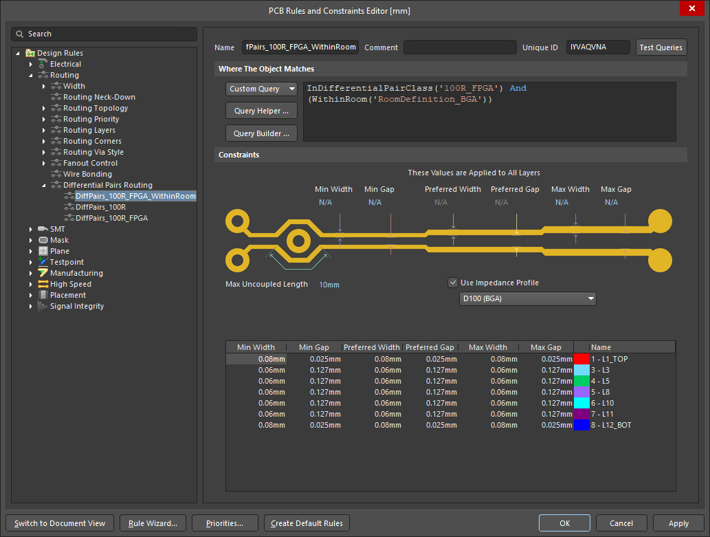
To achieve the same result in the PCB Rules and Constraint Editor you create a query that defines the area of the room. In terms of how the objects in the room are detected, it can be done in two ways, targeting objects that fall completely within the room (using the WithinRoom keyword), or targeting objects that are touching the room (using the TouchesRoom keyword). The slideshow below demonstrates the same routing width, electrical clearance, routing via style, and differential pair properties that were shown in the previous Constraint Manager slideshow.
Arranging Selected Rooms
To arrange selected rooms within the design space, the Design » Rooms » Arrange Rooms command can be used. Select the required rooms, then launch the command to open the Arrange Rooms dialog.
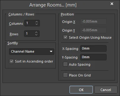 The Arrange Rooms dialog.
Specify how you want the rooms arranged, and in what order they are to be placed. You can also specify the starting position – either by entering the X-Y coordinates in the dialog or by clicking in the workspace – as well as the spacing between adjacent rooms. After clicking OK, the selected rooms will be moved into place.
Columns/Rows |
|
| Columns | The number of columns used to place the rooms. Edit this field as required. |
| Rows | The number of rows used to place the rooms. Edit this field as required. If there are more rooms than will fit into the custom rows and columns arrangement, more rows will be added at the top. |
Sort By |
|
| SortBy | Displays the chosen sort order, i.e. the criteria used to distinguish the first room from the next. The available options are detailed below. |
| Channel Name | Sort the rooms alpha-numerically, based on their channel name. Learn more about multi-channel design. |
| Room Area | Sort the rooms based on their area. |
| Room Component Count | Sort the rooms based on the number of components they contain. |
| Room Width | Sort the rooms by their X (horizontal) size. |
| Room Height | Sort the rooms by their Y (vertical) size. |
| Sort in Ascending order | Enable to sort the rooms in ascending (smallest to largest) order, according to the current SortBy criteria. If this option is disabled, the sort order is descending (largest to smallest). |
Position |
|
| Origin X | Defines the X (horizontal) location where room placement will commence. Edit this field to change the X coordinate, which can be defined in either mm or mil units. To specify the units when entering a number, add the mm or mil suffix to the value. Default units (metric or imperial) are determined by the Units setting in the Properties panel and are used if no units are specified. |
| Origin Y | Defines the Y (vertical) location where room placement will commence. Edit this field to change the Y coordinate, which can be defined in either mm or mil units. To specify the units when entering a number, add the mm or mil suffix to the value. Default units (metric or imperial) are determined by the Units setting in the Properties panel and are used if no units are specified. |
| Select Origin Using Mouse | If enabled, you are prompted to manually set the origin for the room arrangement. The option must be disabled in order to edit Origin X and Origin Y. |
| X-Spacing | Defines the X (horizontal) distance to leave between adjacent rooms. |
| Y-Spacing | Defines the Y (vertical) distance to leave between adjacent rooms. |
| Auto Spacing | If enabled, the rooms are arranged with equal X (horizontal) and Y (vertical) spacing. The option must be disabled in order to edit X-Spacing and Y-Spacing. |
| Place On Grid | Enable to force the rooms to arrange in alignment with the current PCB snap grid. |
Moving Rooms to the Grid
To move each of the selected rooms to the nearest point on the current snap grid, use the Design » Rooms » Move Rooms to Grid command. After launching the command, a confirmation dialog will open asking whether you want to move objects with the selected rooms. Click Yes to move the room(s) and the contained objects to the nearest point on the snap grid, or click No to move the room(s) only.
Copying Room Formats
One of the most powerful features of rooms is the ability to copy the room shape, placement and routing for one room, to other rooms that contains an identical set of components. The command is particularly useful during the layout of a multi-channel design, allowing the placement and routing made in one channel to be propagated to all other channels.
To copy the format of a room to other rooms:
-
Click Design » Rooms » Copy Room Formats from the main menus.
-
The Status bar will prompt to choose a source room. Position the cursor over the source room and click or press Enter.
-
The Status bar will prompt to choose a destination room. Position the cursor over the room that you wish to copy the formatting to, and click or press Enter. If you intend to apply the formatting to multiple rooms, this second click can be on any of the rooms.
-
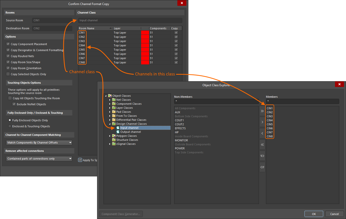
The Confirm Channel Format Copy dialog opens. Use the options to define the format copying required. Format copying will default to be applied from the chosen Source Room to the chosen Destination Room. To copy from the Source Room to each of the rooms in the detected Channel Class, enable the Apply to Specified Channels option and confirm that the required Copy checkboxes are enabled for the target rooms.
-
Click OK in the dialog to update the destination room(s).
-
You can continue to select additional destination rooms, or right-click to finish.
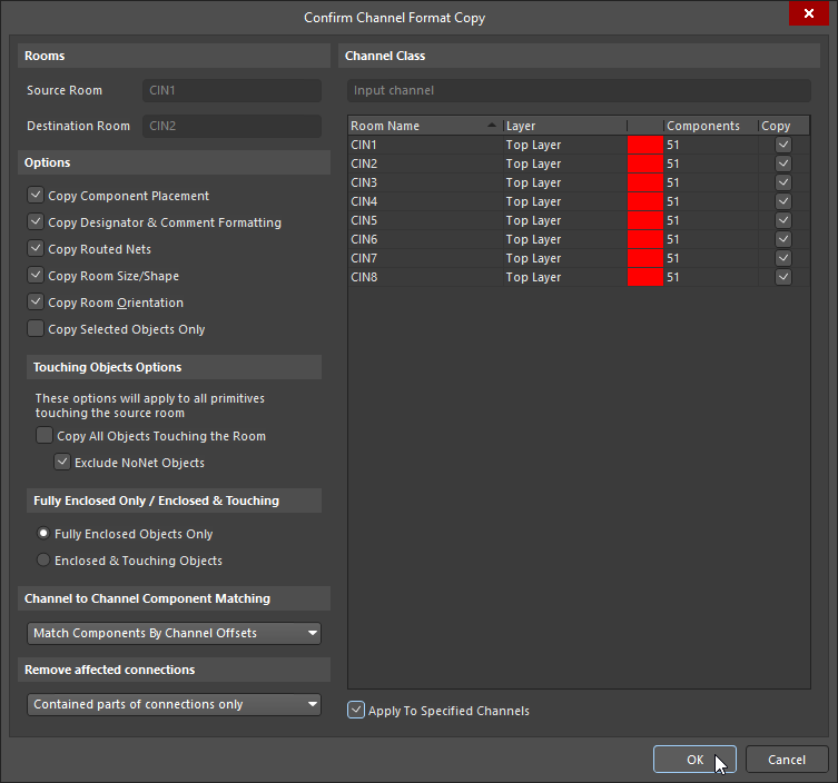
Rooms |
|
| Source Room | The name of the source room (representing the channel from the schematic), whose component placement and routing will be copied. |
| Destination Room | This field contains the name of the destination room (representing the channel from the schematic), that the copied placement and routing will be applied to. If the project is a multi-channel design and the source and destination channels are members of the same Channel Class, then format copying will be applied to the channels enabled in the Channel Class region of the dialog ( |
Options |
|
| Copy Component Placement | Copy the component placement of the source room, to the destination room(s). |
| Copy Designator and Comment Formatting | Copy the designator and comment format of the source room, to the destination room. |
| Copy Routed Nets | Copy the routing layout (tracks/arcs & vias used to route the nets) of the source room, to the destination room. |
| Copy Room Size/Shape | Copy the source room shape and apply this shape to the destination room. If the Copy Room Orientation is enabled in the dialog, the destination room shape will be changed relative to its starting (bottom left) point, i.e. the bottom left point of the destination room will remain unchanged. |
| Copy Room Orientation | Copy the room orientation. Altium Designer detects the orientation of rooms (by the rotation angle of the component with the largest number of pins or, if there is more than one component with the same largest number of pins, the component of the largest area) and uses that to rotate the destination room. |
| Copy Selected Objects Only | Copy the formatting of selected objects of the source room to the destination room. |
Touching Objects Options |
|
| Copy All Objects Touching the Room | Include objects (other than components and routing tracks/arcs & vias) that are fully or partially enclosed by the room. This option must be enabled to copy both net and non-net objects, such as regions, polygons and keepouts, from one room to another room. |
| Exclude NoNet Objects | Exclude objects that do not have a net assigned. |
Fully Enclosed Only / Enclosed and Touching |
|
| Fully Enclosed Objects Only | If the Copy All Objects Touching the Room option is enabled, then enable this option to only copy fully enclosed objects. |
| Enclosed & Touching Objects | If the Copy All Objects Touching the Room option is enabled, then enable this option to copy both enclosed and touching objects. |
Channel to Channel Component Matching |
|
| Match Components by Channel Offsets | Each component in a repeated channel is assigned a channel offset during schematic to PCB design transfer, use the channel offset to identify the same component in each channel. |
| Match Components by Source Designator | Alternatively, use the source (schematic) designator to identify the matching components in each channel. |
Remove Affected Connections |
|
| Whole connections | After the channel format copy has been processed, the software needs to know how to remove the affected connections. If this option is chosen, then the affected connections within and outside the room are removed. |
| Touching parts of connections only | If this option is chosen, then only the affected connections touching the room are removed. |
| Contained parts of connections only | If this option is chosen, then only the affected connections within the room are removed. |
Channel Class |
|
| Channel Class | When a multi-channel design is transferred from schematic to PCB, the repeated circuitry (channels) is identified as a Channel Class in the PCB editor's Object Class Explorer dialog ( |
| Channel Members | This list contains the channels, each identified by its room name. If the source room is part of a defined channel class, the class and all of its members will be listed. The layer (side of board that the room has been placed on), and number of components in each channel, is displayed. Each channel includes a checkbox used to control if format copying is to be applied to that channel, the checkbox becomes accessible if the Apply To Specified Channel option is enabled. |
| Apply To Specified Channel | The default behavior is to copy the format from the Source Room to all channels in the Channel Class that the source room (channel) is a member of. When this option is enabled the Copy checkbox for each channel becomes available, giving selective control over which channels in the class will be targeted by the format copy action. |
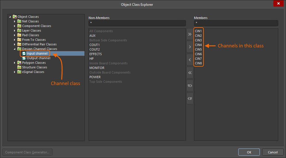 ).
).
Hiding Rooms
Rooms within a given document can be globally displayed, hidden, or displayed in draft mode using options on the View Options tab of the View Configuration panel.
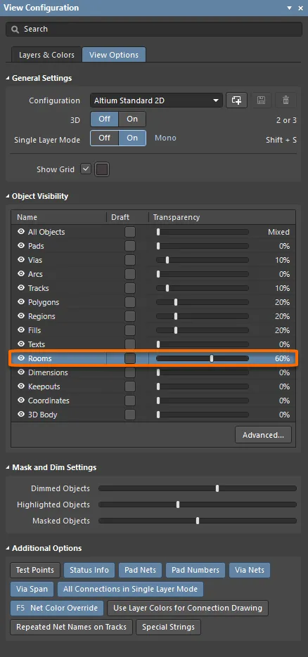 Adjust the Object Visibility slider for Rooms to fade or hide them in the editing space.