
KB: Multi-board Module loses PCB Assignment
 Altium Designer
Solution Details
Empty PCB assignment in schematic modules
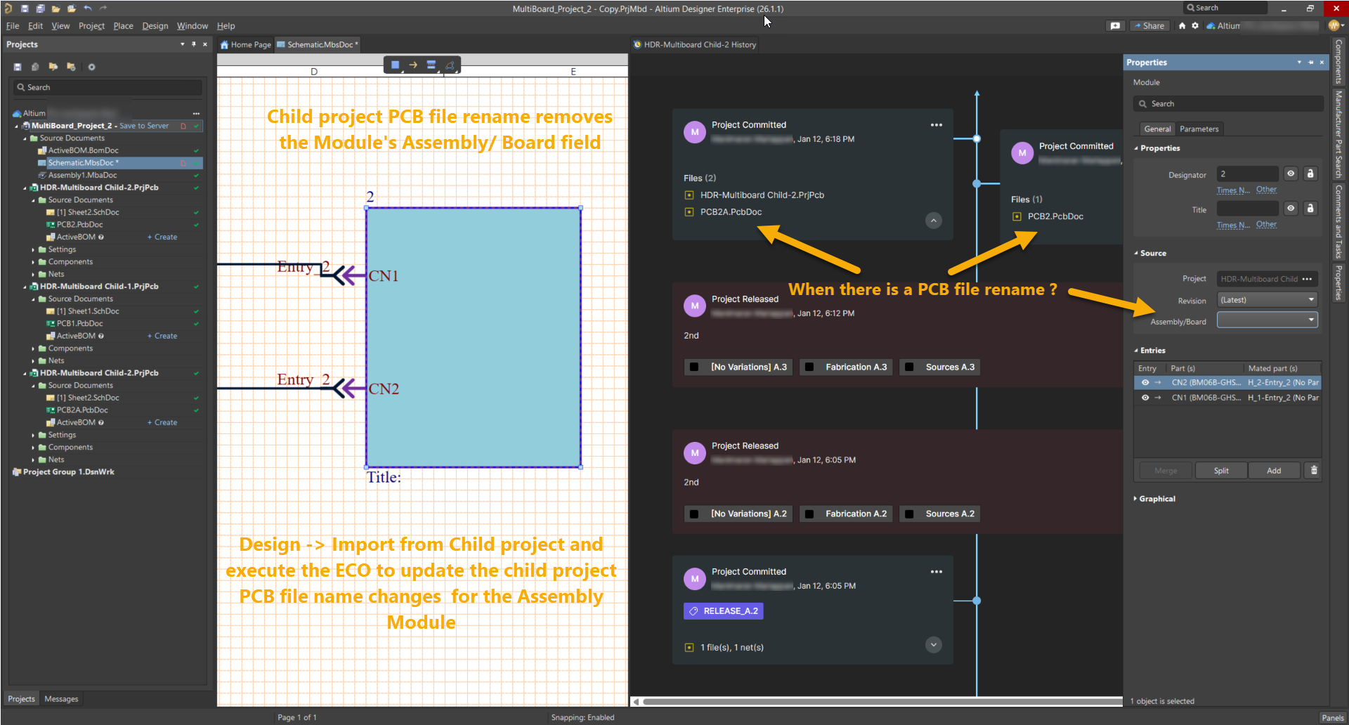
In a multi-board schematic document, a module may display an empty Assembly/Board field even though a PCB board was previously assigned. This typically appears after the document is saved and reopened and affects designs where the PCB file in a linked child project has been renamed.
Renamed PCB breaks ECO-based synchronization
The multi-board schematic maintains its link to each child PCB using the PCB file name and unique internal identifiers. Synchronization between child projects and the multi-board schematic is handled through an Engineering Change Order (ECO). When a PCB file is renamed and saved, the original reference becomes invalid because the system cannot automatically map the old file name to the new one. Until an ECO import is performed from the child project, the multi-board schematic cannot resolve the renamed PCB, breaking synchronization.
Update schematic before updating assembly
- Import changes from child projects into the multi-board schematic using the ECO workflow.
- After the schematic is fully synchronized, update the multi-board assembly.
This order is critical because the physical multi-board assembly (*.MbaDoc) is generated and synchronized from the logical multi-board schematic (*.MbsDoc). Stable PCB references in the schematic are required to preserve mates defined in the assembly.
Import child project changes using ECO
- Open the multi-board schematic document where the module shows an empty Assembly/Board field.
- Select Design » Import From Child Projects.
- Review the Engineering Change Order list and confirm that the renamed PCB file is detected.
- Validate and execute the ECO to apply the changes.
- Verify that the module properties now display the correct PCB file name.
- Open the multi-board assembly document.
- Select Design » Import Changes From <Project_Name>.PrjMbd.
- Validate and execute the changes to synchronize the physical assembly.
Additional Notes
- Mates are defined in the multi-board assembly and depend on stable PCB references from the multi-board schematic.
- Importing changes from the schematic into the assembly before updating the schematic can remove existing mating connections and require manual rework.
- Avoid renaming PCB files after linking them to a multi-board schematic whenever possible.
- If renaming is required, always follow the import order described above.
- Review ECOs carefully before execution to ensure all PCB references and connectivity data are correctly synchronized.