KB: Creating and Updating Schematic Symbols with Excel Pin Data
Updated: апреля 21, 2026
This article describes how to efficiently create schematic symbols in Altium Designer using the Symbol Wizard and the SCHLIB List panel. These methods are particularly useful for components with a high pin count, enabling users to define pin layouts, bulk‑paste pin numbers and names from Excel, and configure pin electrical types and groups. By leveraging these built‑in tools, symbol creation time is reduced and the risk of manual data entry errors is minimized.
Solution Details
Manual symbol creation challenges
Creating schematic symbols manually can be time‑consuming and error‑prone, especially for components with many pins. Users often need to enter pin numbers, names, and electrical types individually, which increases the likelihood of inconsistencies between the schematic symbol and the original pin data provided in datasheets or Excel files.
Why bulk pin editing is needed
High pin‑count components commonly have pin information maintained in spreadsheets. Without automation, transferring this data into a schematic library requires repetitive editing. Altium Designer provides tools that allow users to paste and manage pin data in bulk, improving accuracy and efficiency.
Available tools for symbol generation
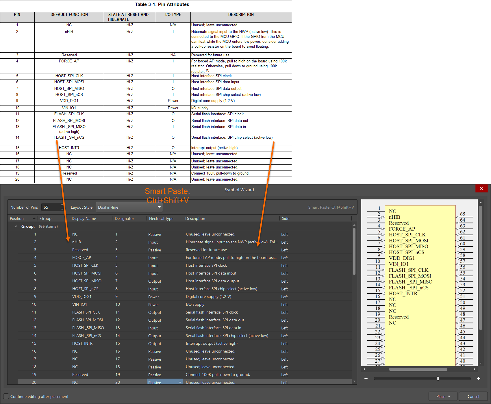
- Use the Symbol Wizard to automatically generate a schematic symbol by defining the pin count and layout, then pasting pin data from Excel.
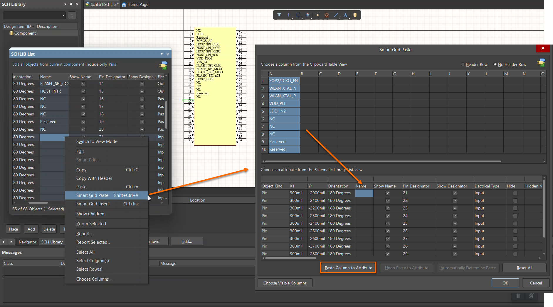
- Use the SCHLIB List panel to bulk‑edit pins that are already placed in the schematic library.
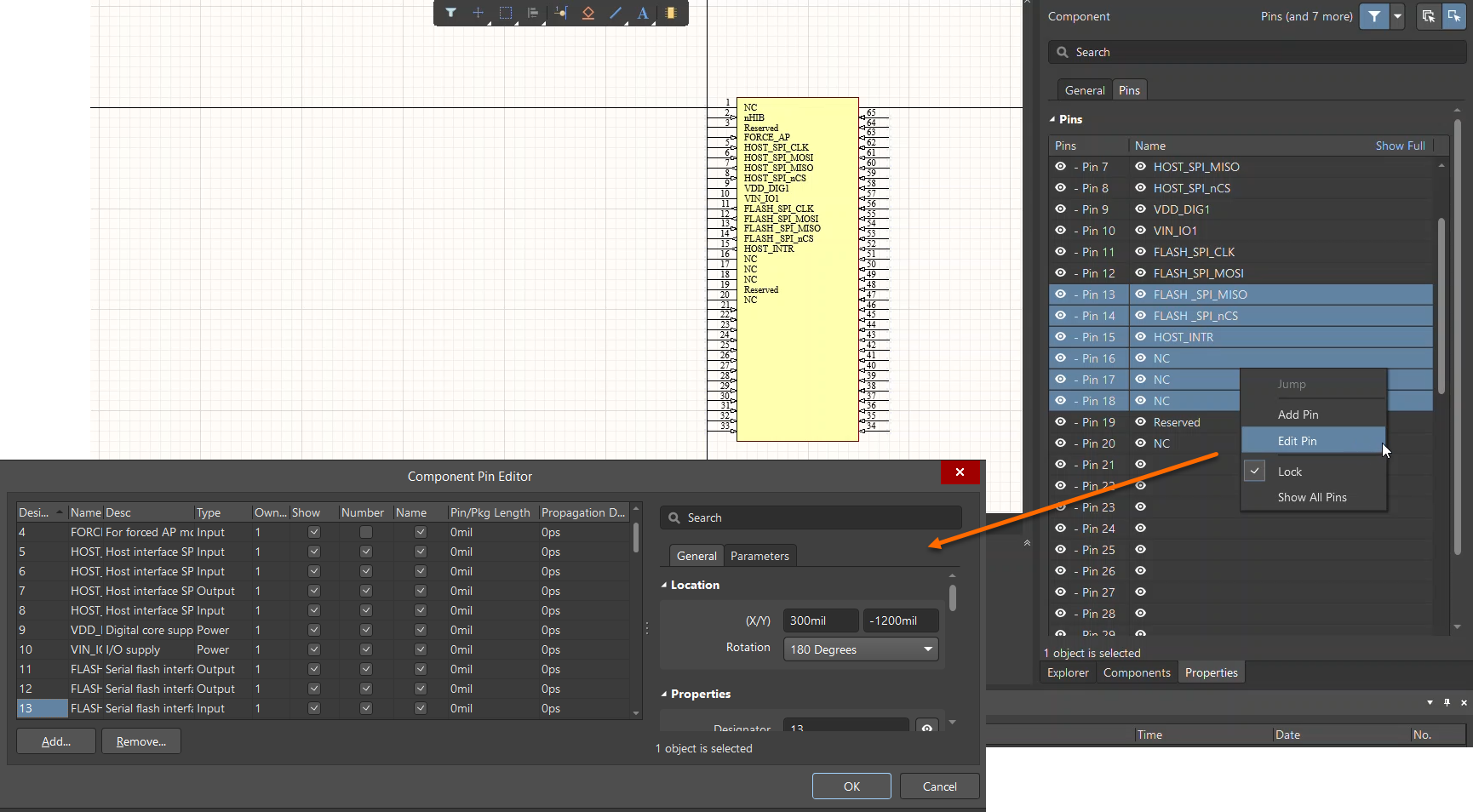
- Use the Component Pin Editor to select multiple pins and set electrical types and other properties at once.
Steps to create symbols efficiently
- Open the Schematic Library.
- Go to Tools » Symbol Wizard...
- In the Symbol Wizard dialog, specify the required number of pins and select the desired layout style.
- Open the pin details in Excel.
- Copy the pin numbers from Excel and paste them into the Designator column.
- Copy the pin names from Excel and paste them into the Display Name column.
- Optionally assign pin groups and set the electrical type for the pins.
To update pins of an existing symbol using the SCHLIB List panel:
- Open Panels » SCHLIB List.
- Set the scope to All objects and Current Component, and filter the list to include Pins only.
- Enable Edit Mode and sort the pin order as required
- Copy the pin data from Excel and paste it into the corresponding columns in the SCHLIB List panel.
- Select multiple pins in the Properties panel and open the Component Pin Editor to configure electrical types and other properties in bulk.