
KB: Displaying Individual Wires from Twisted Pair Cables in Harness Layout Drawings
Solution Details
Individual wires missing from layout drawings
When a connector is connected to ferrules or ring terminals through a twisted pair cable, the Harness Layout Drawing may display only the cable bundle. The individual wires contained within the twisted pair are not visible, making it difficult to understand how each wire is physically terminated at the ferrules or ring terminals.
Connection points define wire grouping behavior
The Harness Layout Drawing is generated from the Harness Wiring Diagram, but connection points act as the logical mapping layer between the wiring definition and the physical layout. Connection points determine how pins and wires are grouped when multiple cable types, such as twisted pairs and single wires, originate from the same connector. If connection points are not explicitly placed and configured, the layout cannot correctly break out twisted pair wires or represent mixed cable types.
Additionally, Bundle Objects shown in the layout are derived from the Wiring Diagram definitions and connection point mapping. Individual wires will only appear in these bundles if they are explicitly defined and properly associated with connection points. Changes in the Wiring Diagram, such as modifying twisted pair definitions, may not automatically propagate and can require re-import or update actions in the layout to ensure consistency.
Recommended configuration and modeling practices
- Fully define all wires and twisted pairs in the Harness Wiring Diagram.
- Assign wire and twisted pair designators consistently to improve traceability during layout review, validation checks, reports, and manufacturing outputs.
- Use explicit connection points in the Harness Layout Drawing to control wire grouping and twisted pair breakouts.
- Ensure each connection point has a unique designator to prevent incorrect mapping or grouping.
- Verify and adjust connection point pin assignments after importing the Wiring Diagram, especially when connectors use both twisted pair and non-twisted wiring.
- Re-import or update the layout after making changes in the Wiring Diagram to maintain synchronization.
- Use Harness Design Rule Checks (DRC) to validate twisted pair definitions and pin assignments before layout import.
Step-by-step wiring and layout procedure
- Open the Harness Wiring Diagram (
*.WirDoc) and place the connectors and ferrules or ring terminals.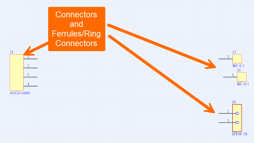
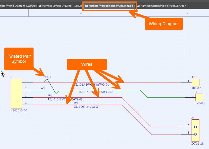
- Place wires between the connector pins and the ferrules or ring terminals. Assign wire designators and comments as required.
- Place the twisted pair symbol so that it fully covers the wires that form the twisted pair cable.
- Assign a designator and comments to the twisted pair symbol for clear identification.
- Save the Harness Wiring Diagram.
- Open the Harness Layout Drawing (
*.LdrDoc). - Import the Wiring Diagram using Design » Import Wiring Diagram.
- Verify that the connectors, ferrules or ring terminals, and their initial connection points are imported into the layout.
- For each connector that connects to ferrules or ring terminals through a twisted pair, manually place a connection point using Place » Connection Point. Position the connection point at the physical location where the twisted pair cable breaks out into individual wires.
- Assign a unique designator to the connection point if one is not automatically generated.
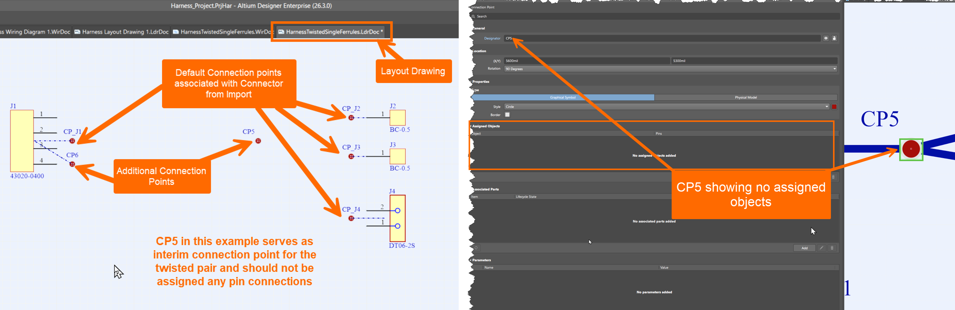
- Open the connection point properties and review the assigned connector pins and wire associations. Confirm that only the twisted pair wires are grouped under this connection point and separated from any single wires or other cable types.
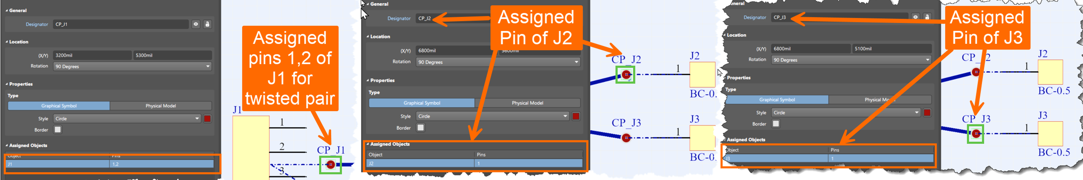
- Reassign pins if necessary to correct the grouping.
- Place cables between the connector connection points and the intermediate connection points.
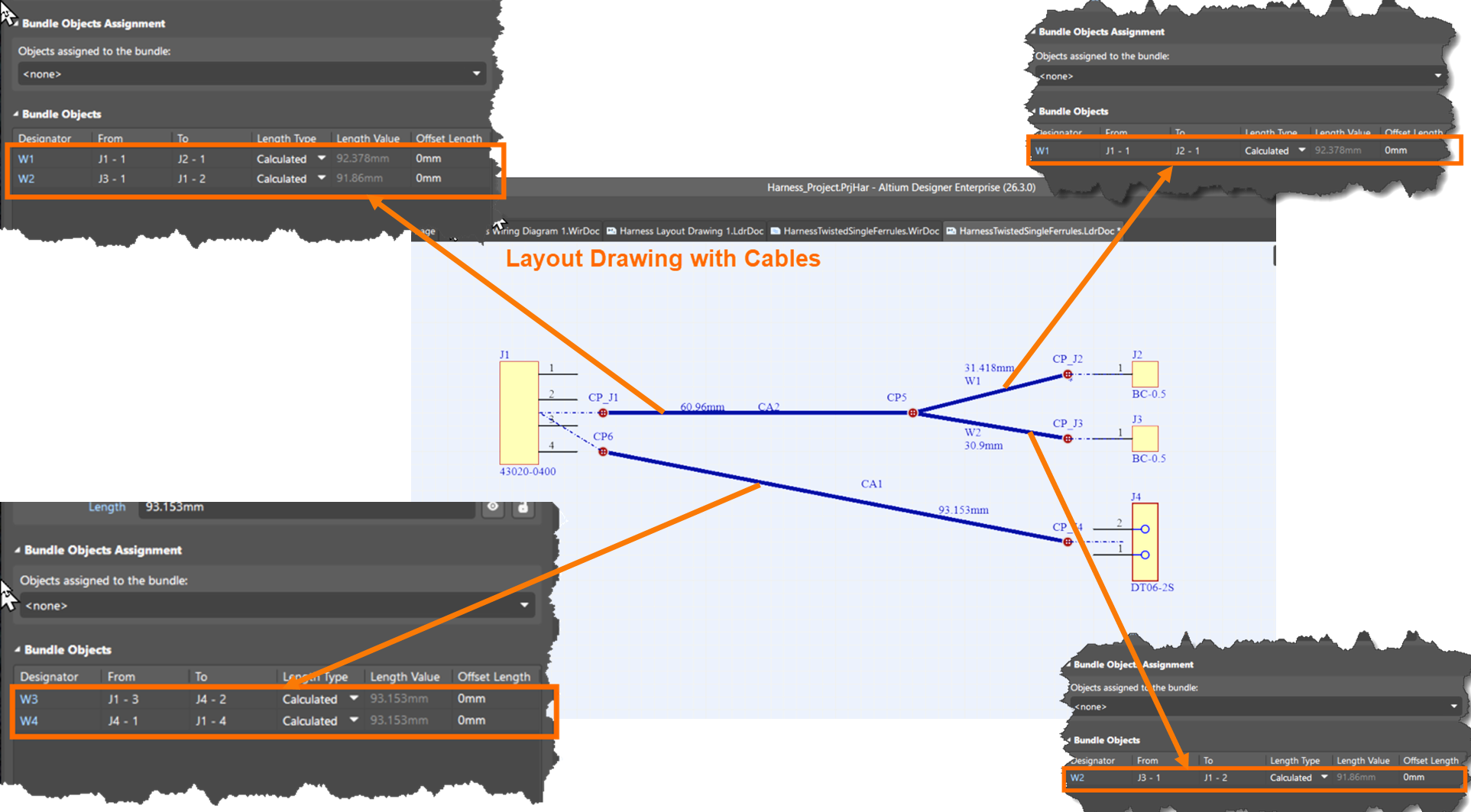
- Review the cable bundle properties and confirm that the correct individual wires appear under Bundle Objects.
Additional Notes
This procedure assumes that the required connectors and terminals already exist in a Local, Workspace, or On-Prem Server Library, and that the project contains a blank Harness Wiring Diagram and Harness Layout Drawing.
References
- Harness Design Overview (Altium Documentation) – Provides an overview of harness design workflows, including wiring diagrams and layout drawings.
- Defining the Wiring Diagram – Explains how wires, cables, and connectivity are defined in a Harness Wiring Diagram (
*.WirDoc). - Creating the Harness Layout Drawing – Describes how layout drawings (
*.LdrDoc) are generated and configured based on wiring diagrams. - Harness Design Objects Reference – Details key objects such as wires, cables, connection points, and bundles used in harness design.
- KB: Missing Splice Objects Under Wiring Bundle in Harness Layout Diagram – Explains how connection point assignments affect which objects appear in bundle views.