
KB: Understanding Component Height vs 3D Body Height in Altium Designer
Solution Details
Inconsistent clearance results in mixed component setups
Designers may notice inconsistencies in component clearance and collision checks, particularly when some components have 3D bodies defined and others do not. In mixed scenarios, it may be unclear why certain components are included or excluded from Z‑axis clearance checks, or why manually defined heights appear to be ignored.
Different height sources serve different purposes
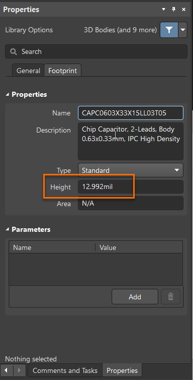
Altium Designer supports two separate height definitions for components. The general Height property is defined manually in the Properties panel of a footprint and acts as a fallback value. When a component footprint includes a 3D body (extruded or imported via STEP or Parasolid), Altium derives the height directly from the tallest 3D object. This 3D‑derived height always overrides the manually entered Height property, ensuring that clearance checks reflect real physical geometry. An additional rule option, Do not check components without 3D body, controls whether components lacking 3D bodies participate in clearance checking at all.
Choose the correct height method for your design
- Use the Height property only as a placeholder when no 3D body is available.
- For accurate clearance and collision detection, ensure all critical components have correctly defined 3D bodies.
- Configure the Do not check components without 3D body option based on whether fallback height checking is acceptable for your workflow.
Steps to define heights and configure clearance rules
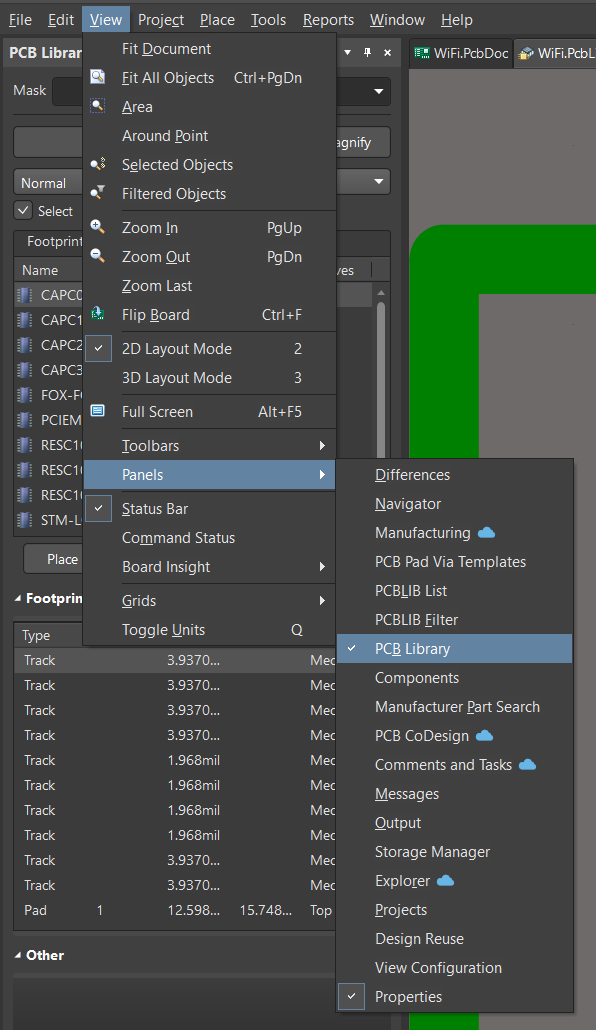
- Open the required footprint in the PCB Library.
- In the Properties panel, set the Height value if no 3D body is present.
- Add or verify a 3D body by inserting an extruded 3D shape or importing a STEP/Parasolid model into the footprint.
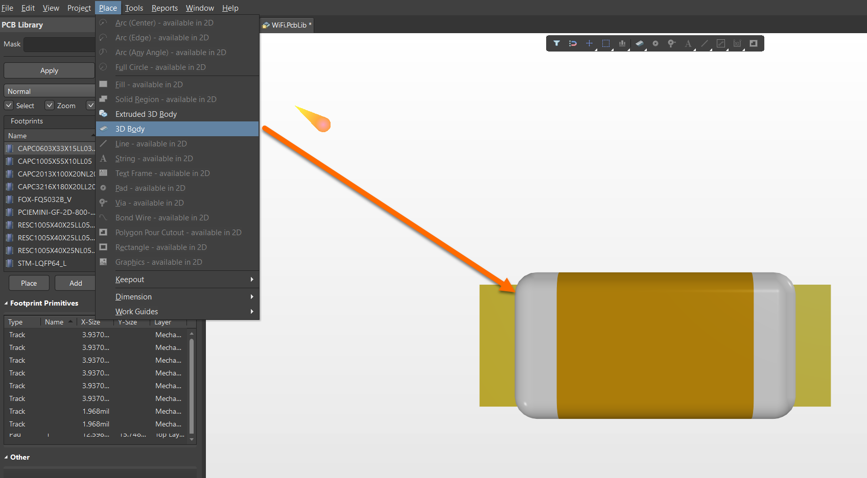
- Note that the tallest 3D object in the footprint defines the effective clearance height.
- Open Design » Rules » Placement » Component Clearance.
- Enable or disable Do not check components without 3D body as required.
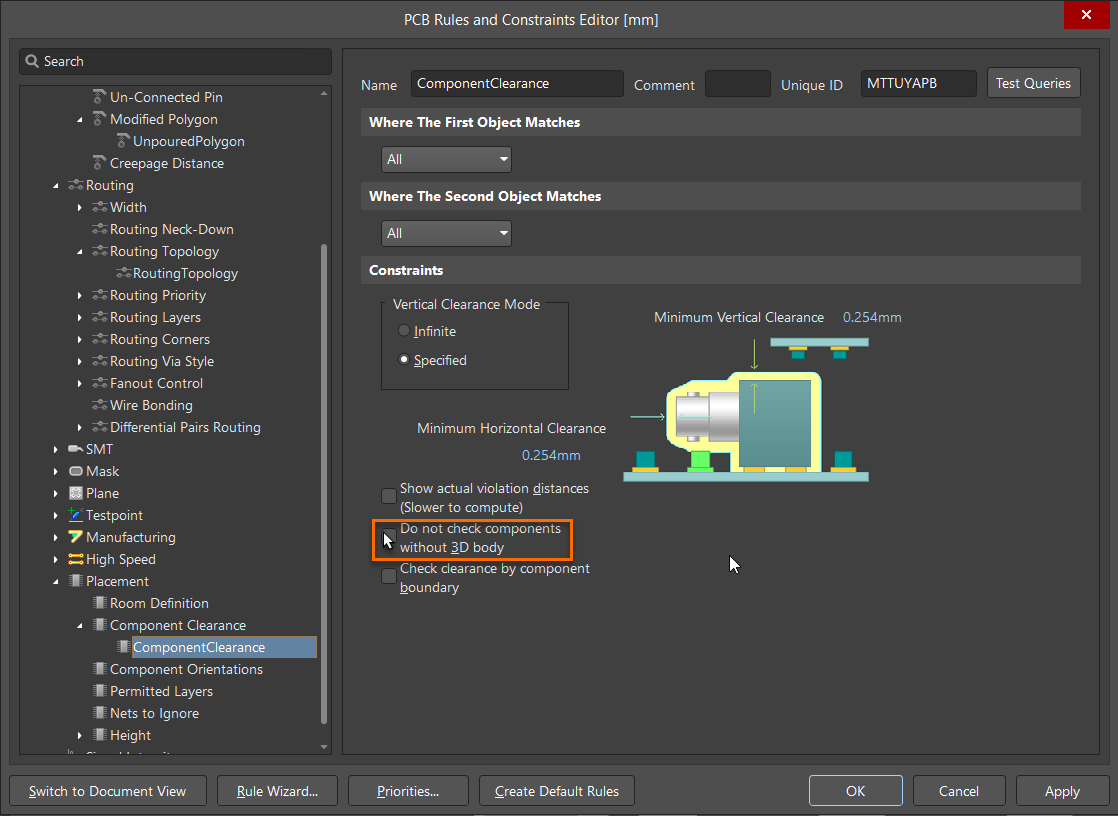
- If the option is disabled, Altium uses the component bounding box and the Height property for Z‑axis clearance when no 3D body exists.
- For ECAD‑MCAD workflows, be aware that Altium MCAD CoDesigner uses the Height property only when no 3D body is available.
Additional Notes
The Height property is specifically used by Altium MCAD CoDesigner in cases where a component does not include a 3D body, enabling basic spatial representation during ECAD‑MCAD exchange.