Parent page: Managed Projects
Altium Concord Pro's Web Viewer interface provides universal access to PCB project documents through a standard web browser. Much more than just a web-based viewer, Web Viewer's advanced browser technology allows users to navigate through the project structure, interact with design documents, extract information about elements in the design and highlight areas or objects for commenting notes.
When viewing documents the visual quality of schematics and PCBs are not compromised by its web format, which also provides full pan and zoom capabilities and the ability to search, cross-probe, select and inspect components and nets throughout the design.

As an independent browser based viewing platform, the Web Viewer interface offers interactive read-only access to design documents without the need to open the project in the design editing environment. Others that are working on the design, such as the engineer who 'owns' it, will not be affected by actions in the Web Viewer space – except for any related comment notifications, where applicable.
Web Viewer Access
The Web Viewer can be accessed directly in Altium Concord Pro or indirectly from within Altium Designer. In the latter case, the Show in Web Browser menu commands or the Explorer panel's Open in Web button will generate and then open a specific viewer URL in the server's browser interface. That URL can be shared with other users, such as a team manager or librarian for example, allowing them to interact in detail with the current project documents and data via the server Web Viewer interface. All that's required is a Concord Pro user account and appropriate access privileges.
In Altium Concord Pro, the Web Viewer interface is used in the following instances:
- When viewing the current state (WIP) of a design project source through the Projects Management interface, when managing a specific project.
- When viewing the design snapshot for a released design package, through the Manufacturing Portal.
The following sections detail how each of these instances is accessed, and how the Web Viewer interface presents in each case.
Viewing WIP Design Project Source Files
In this instance, the Web Viewer interface is presented through the Design view of the Projects Management page. The latter can be accessed from the Projects page of the server's browser interface by double-clicking on the project entry, single-clicking on the project entry name, or by selecting the required project and then choosing the Open option from the  menu above the listing or the
  menu associated with the project entry.
 Accessing the CAD-centric Projects Management page for a project from the Projects page. The Web Viewer interface is presented through the page's Design view.
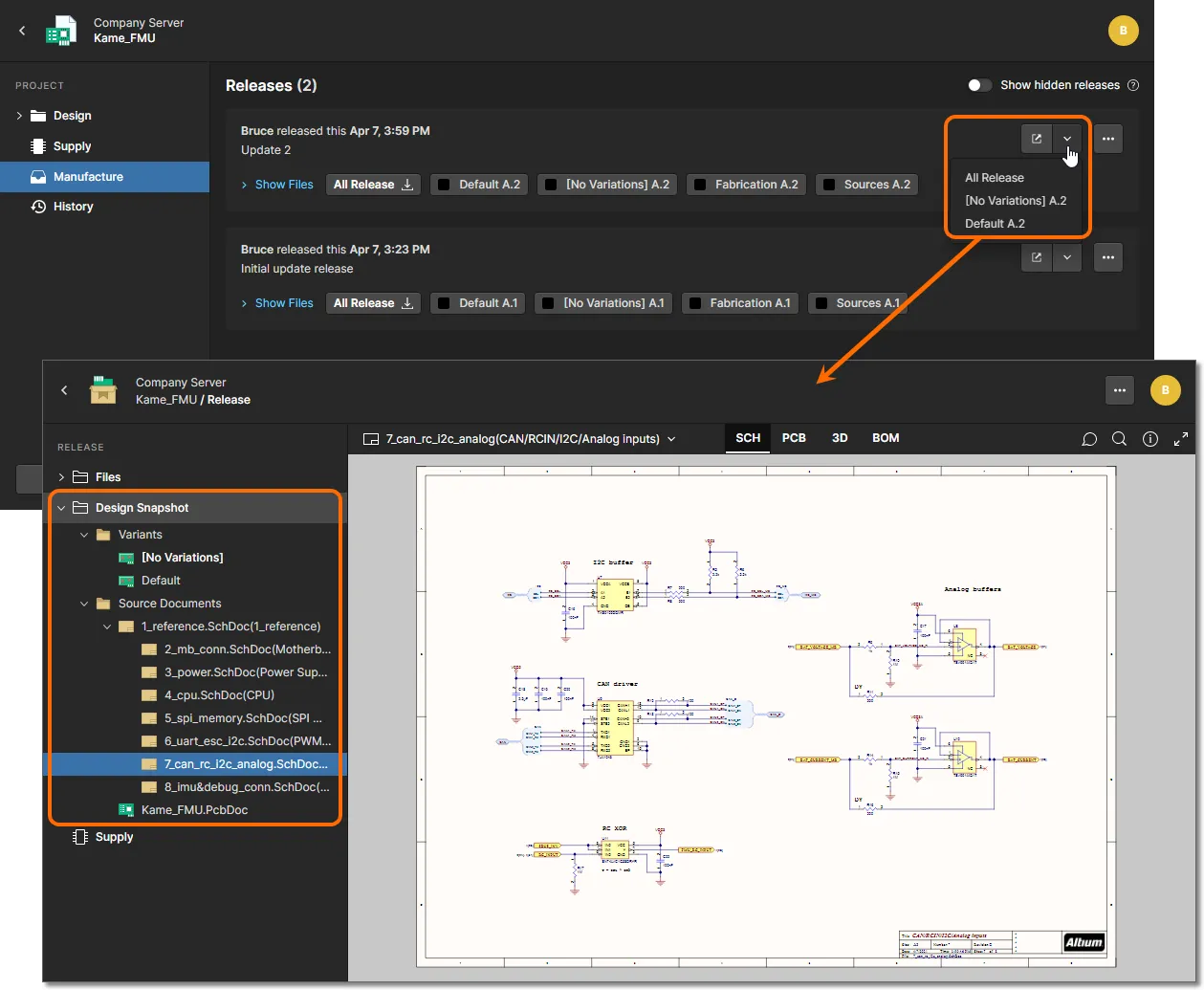
Viewing Design Snapshot for a Release Package
In this instance, the Web Viewer interface is presented through the Design Snapshot view of the Manufacturing Portal, for the chosen release package of the managed project actively being inspected. To access the portal:
- From the detailed Projects Management page for the required project (double-click on the project to access), switch to the Manufacture view.
- To open a specific release package for viewing, click on its associated
 button to open the full release package. Alternatively, click the
  button and choose what to view – either the full release package (All Release) or a specific assembly variant. An opened project release is presented in a new Manufacturing Portal browser tab.
- Within the Manufacturing Portal, switch to the Design Snapshot view. Note that you are not viewing the latest version of the source design data, but rather the snapshot of it, at the time when the design was released to create this specific release package.
Web Viewer Features
The Web Viewer interface offers a range of integrated capabilities that allow detailed access to design data. Other features such as the Comments system – when used from the Design view of the Projects Management page – communicate directly, and in real-time, with Altium Designer. The following sections take a look at the superset of functionality – available when viewing the design source.
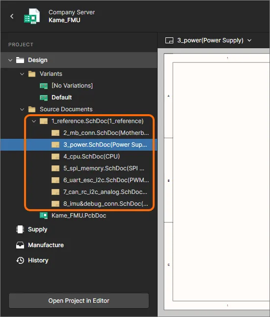
Data Views
The Web Viewer interface presents information across distinct data views, to show (when viewing design source) the source schematics, board in 2D, board in 3D and Bill of Materials respectively.
SCH
This view presents the source schematic sheet(s) for the design.
 The SCH data view presents the currently selected schematic source document.
Switching Schematics
If more than one schematic sheet exists for the design, the ability to switch between the documents can be performed in two ways:
- From the navigation tree in the left-hand pane. Select a schematic entry to make it the active document in the main viewing area.
- By choosing a schematic entry from the preview drop-down menu, located at the top left of the view. The currently selected document – the active document being viewed within the SCH data view – is distinguished in the list with a blue border around its entry.

This method of switching between schematics is the only method available when the
Web Viewer interface is placed in
Full Screen mode (by clicking the

control at the top-right of the view).
In-Document Navigation of Design Hierarchy
When inspecting a schematic document that is part of a hierarchical design project, the rendered document display itself can provide interactive navigation between the levels in the project structure hierarchy:
- Click on a sheet symbol object to load the target schematic document.
- Click on a sheet entry object within a sheet symbol to be taken to the corresponding port on the target child schematic below.
- Click on a port object to be taken to the corresponding sheet entry of the sheet symbol in the parent schematic above.
Support for Multi-channel Designs
The Web Viewer supports the viewing of multi-channel designs. A separate schematic document is presented for each physical channel. The physical sheet name – the compiled tab for that schematic document when viewed through Altium Designer – is included as a suffix to the document name. The result is similar to generating a PDF document of the physical schematic sheets, only with the enhanced interaction that the Web Viewer provides.
 Example multi-channel design, with each physical channel being presented on a different schematic sheet.
Browsing Controls
Browsing controls for the main viewing area are as follows:
- Mouse wheel forwards/backwards to zoom in/out.
- Click & hold (or right-click & hold), then drag to pan document.
- Click to select.
- Press R to reset the view of the document (to show the entire document).
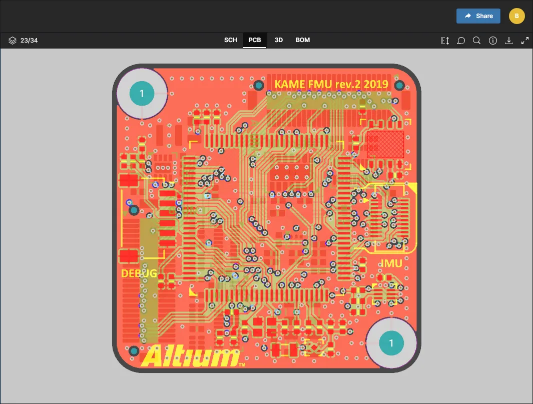
PCB
This view presents the PCB in 2D.
Browsing Controls
Browsing controls for the main viewing window are as follows:
- Mouse wheel forwards/backwards to zoom in/out.
- Click & hold (or right-click & hold), then drag to pan document.
- Click to select. Click repeatedly to cycle through collocated objects and/or to select the parent net.
- Press + or – on the numeric keypad to step forward or back through the list of layers, in single layer mode.
- Press R to reset the view of the document (to show the entire document).
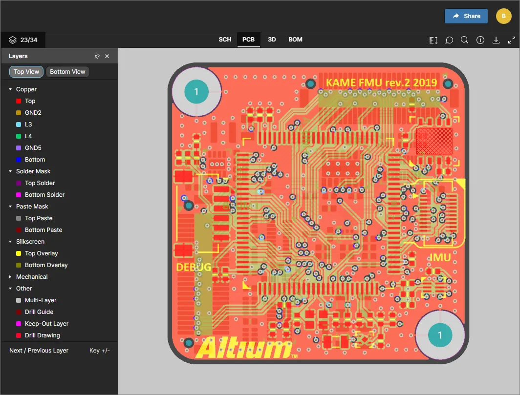
Controlling Layer Visibility
Control over the view and layer visibility for the PCB data view is performed through the drop-down Layers pane. Access this pane by selecting the control at the top-left of the view ( ). This control reflects how many layers are currently visible out of the total number of layers.
 The Layers pane for controlling layer visibility.
You can pin the
Layers pane so that it is always present as you view the PCB in the main viewing area. To do so, click on the

control (unpinned) at the top-right of the pane – the control will change to

(pinned). Click on the control again to unpin.
Layers are grouped into the following categories:
- Copper – all used signal and internal plane layers.
- Solder Mask – Top Solder, Bottom Solder.
- Paste Mask – Top Paste, Bottom Paste.
- Silkscreen – Top Overlay, Bottom Overlay.
- Mechanical – all used mechanical layers.
- Other – including Mutli-Layer, Drill Drawing, Drill Guide and Keep-Out Layer.
Use the  and
and  buttons to quickly toggle between viewing the board from the top or bottom respectively.
Switch between Top and Bottom views of the board using the provided buttons. Here, the default Top View is shown.
The following points relate to working with layer visibility in the Layers pane:
- A currently visible layer is shown in the pane undimmed (
 ). A currently hidden layer is shown in the pane as dimmed (
 ), along with the
  icon displayed at its far right.
- A currently visible layer can be hidden by clicking on its entry, or by hovering over its entry and clicking the
 icon at its far right. Conversely, a currently hidden layer can be made visible by clicking on its entry, or by hovering over its entry and clicking the icon at its far right.
- An entire group of layers can be hidden by hovering over the group entry and clicking the icon at its far right. Conversely, if all layers in a grouping are currently hidden, they can be made visible by hovering over the group entry and clicking the icon at its far right. Note that if a group has a mixture of visible/hidden layers, the icon will be present for the group. Click to hide all other layers, then click again (now showing as ) to make all layers visible.
- To quickly view in 'Single Layer Mode', hover over the specific layer of interest, then click the
 control. All other layers will be hidden. Click the control again to come out of 'Single Layer Mode'.
Note that the Multi-Layer will remain visible (or be unhidden if applicable) if a copper (signal) layer or solder mask layer is visible.
 The PCB data view supports single layer mode. Here, access to the Only control is shown.
- To reset layer visibility back to how it was when the design was initially accessed, click the
 control at the top-right of the Layers pane.
Taking Measurements
When viewing the board in 2D – using the PCB data view – you are able to take measurements using the  button. This opens the Measurements pane, the cursor changes to a cross-hair and enters measurement mode. Three measurement modes are supported:
- Free – freely measure between any two points within the data view, without any snapping guidance whatsoever.
- Point to Point – measure between any two points within the data view, with guidance snapping as you move the cursor over an object. The cursor will change as follows:
-
 – the center of a pad or via.
-
 – the vertex point of a primitive object.
-
 – the mid-point of a track segment.
-
 – a free point within the view.
- Object to Object – measure between any two chosen objects within the data view. Supported objects are pad, via, track, fill and region, which will become highlighted for selection as you move the cursor over them.
Switch modes using the buttons at the top of the pane. When accessing the feature for the first time, the Free mode will be used by default. Subsequent use of the feature will use the mode last used.
Measurement is performed as follows:
- In Free or Point to Point modes, position the cursor to where you wish to start measuring (Point 1) and click. The point is marked using a small white cross. In Object to Object mode, choose the first object (Object 1), which will become selected.
- In Free or Point to Point modes, move the cursor to the required end point (Point 2) and click again. As you move the cursor, a measuring line is displayed as an aide, showing the current XY distance (from Point 1 to the end of the line). In Object to Object mode, choose the second object (Object 2), which will become selected.
Right-click before defining Point 2/Object 2 to start afresh – ready to define Point 1/Object 1 again.
- The Measurements pane reports the XY distance measured, the X (horizontal) distance, and the Y (vertical) distance. For the Object to Object mode, the XY distance will be the shortest point between the two chosen objects.
Measurement units will initially be those used for the design itself, but can be switched between metric (mm) and imperial (mil) from the
Info pane of the interface (accessed by clicking

in the top-right control cluster).
- Continue measuring the distance between other points or objects, or click the button again (or Esc) to exit measurement mode.
 Example measurement taken in Point to Point mode.
The last five measurements are listed in the Previous Measurements region of the Measurements pane. The most recent is at the top of the list. Click on an entry to retrieve that measurement – both in the pane and graphically in the main viewing area.
Measurements are available during the current session of the web page only. If you refresh the browser tab, the previous measurements will be cleared.
3D
This view presents the PCB in 3D.
 The 3D data view presents a 3D view of the PCB.
Browsing Controls
Browsing controls for the main viewing window are as follows:
- Mouse wheel forwards/backwards to zoom in/out.
- Click & hold, then drag to rotate the board.
- Right-click & hold, then drag to pan document.
- Click to select.
- Press R to reset the view of the document (to show the entire document).
BOM
This view presents the Bill of Materials for the design. This is built on-the-fly from the source schematic documents – an ActiveBOM document (*.BomDoc) is neither required or used.
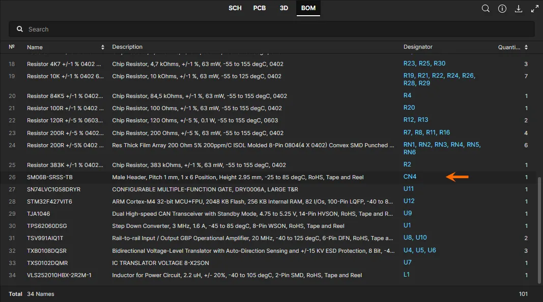
 The BOM data view presents the Bill of Materials for the design – created on-the-fly from the source schematics.
The BOM reflects all components required to assemble a single board. Pricing information is sourced from Octopart.
The following points relate to working with the view:
- Clicking on the Name entry for a component will access the page for the corresponding real-world part on the Octopart site (opens in a separate tab).
- Clicking on a designator will cross-probe to that component on the other data views.
- You can sort by Name, Price, or Quantity – click a header once to sort in ascending order. Click again to sort in descending order.
- Use the Search field above the listing to quickly find a component of interest. Search applies across Name, Price, Description and Designator fields.
Common Interface Elements
The following controls are common to all data views:
-
 – use this control (located in the top-right control cluster) to access the Search facility, allowing you to search for components and/or nets. This facility is available for the SCH, PCB and 3D data views (not BOM). For more information on using the search facility, see Searching.

- – use this control (located in the top-right control cluster) to access the Info pane.

- The pane is further divided into two sub-views:
- Controls – gives a helpful listing of controls when browsing the SCH, PCB and 3D data views (some controls are view-specific).
- Board Info – gives useful summary information about the uploaded design in terms of: Board Size (X and Y dimensions of the board); Number of Layers (Signal + Plane) and a sub-total of Signal layers only; Number of Components (total, including all types of component) with a breakdown of those components on Top and Bottom of the board; Number of Nets (total).
At the bottom of the pane, use the available controls to switch Units between metric (mm) and imperial (mil). Measurement units will initially be those used for the design itself.
-
 – use this control (located in the top-right control cluster) to download data via the Download pane. When viewing design project source files, the pane provides controls for downloading a Zip archive containing a snapshot of the WIP design project (the Working Copy), and for generating and downloading Zip archives of a PDF of the schematic prints and the PCB in STEP format. All release packages that have been generated from the project will also be listed – click an entry (here, A.2 or A.1) to open it for inspection (and/or downloading) on a separate browser tab.

While the downloaded Working Copy is always for the base design, the generated output (Schematic and STEP) is based on the currently chosen variant.
A download is to your Web browser's default downloads folder.
- – use this control (located in the top-right control cluster) to switch to Full Screen mode.
-
 – when in Full Screen mode, use this control (located in the top-right control cluster) to exit Full Screen mode (or press Esc).
Variant Support
If the project includes defined variants, then you will be able to switch between these when viewing the design across the various data views. The left-hand navigation pane presents a listing of the available variants. By default, this will be set to [No Variations] – presenting the base design.
Choose a defined variant from the list of all variants defined for the project – the current data view will update to reflect that variant, including the visual options enabled for not fitted components (SCH and PCB data views).
![By default, the base design ([No Variations]) will be presented (shown here in the SCH data view). Use the controls in the left-hand navigation pane to switch to a different variant.](https://files.doc.altium.com/sites/default/files/wiki_attachments/303034/ACP_DataView-SCH_VariantSelection1_4-0.webp "By default, the base design ([No Variations]) will be presented (shown here in the SCH data view). Use the controls in the left-hand navigation pane to switch to a different variant.") By default, the base design ([No Variations]) will be presented (shown here in the SCH data view). Use the controls in the left-hand navigation pane to switch to a different variant.
By default, the base design ([No Variations]) will be presented (shown here in the SCH data view). Use the controls in the left-hand navigation pane to switch to a different variant.
In the 3D and BOM data views, the component will be present/listed depending on whether it is fitted or not.
Selection
Selection of an object within the design can be performed from the SCH, PCB and 3D data views as follows:
From the SCH data view (component and net selection) – hover the cursor over a component or wire and click to select. Masking is applied to leave only that component or net fully visible. Information for the selected component/net will appear in the right-hand pane.
- Potential objects for selection – components and wires – are highlighted as you move the cursor.
- A selected net will be selected across all schematic documents on which it appears.
 The SCH data view supports the selection of components and nets. Here, a selected component is shown.
From the PCB data view (component, pad, via, track segment and net selection) – hover the cursor over a supported object type and click to select. Masking is applied to leave only that object fully visible. Information for the selected object will appear in the right-hand pane.
Only components are highlighted as you move the cursor. Only an individual component, pad, via, track segment, or net can be selected (no cumulative selection). For a selected pad, via, or track segment, associated net information is presented. To select the entire net, continue clicking to cycle through the selectable objects in a specific location.
Quick net selection in the PCB data view can also be achieved by either selecting the net in the SCH data view and switching to the PCB data view, or by searching for the net using the Search facility.
For collocated objects, clicking repeatedly will cycle through those objects.
 The PCB data view supports the selection of components, pads, vias, track segments and nets. Here, a selected component is shown.
From the 3D data view (component, pad, via selection) – hover the cursor over a component, pad, or via and click to select. Masking is applied to leave only that object fully visible. Information for the selected object will appear in the right-hand pane. In this viewing mode, objects are not highlighted as you move the cursor.
 The 3D data view supports the selection of components, pads and vias. An example of component selection is shown here.
The view mode controls at the top of the right-hand pane enable you to quickly view a selection within another data view (where supported). For example, selecting a component or net in the SCH data view will allow that component/net to be inspected in the PCB and 3D data views also. And for a selected pad, via, or track segment within the PCB data view, you'll be able to quickly view that object within the 3D data view. For more information on this cross-probing support, see the next section.
Cross-probing
When you select a supported object within the active data view, that object is selected (where applicable) on one or more other data views as well – enabling you to quickly cross-probe to that same selection. Cross-probing support is delivered through button controls located at the top of the right-hand pane – displayed when an object is currently selected in the main viewing window.
You can also click on an upper tab for a data view directly to see the result of cross-probing.
.") Cross-probing controls (for a selected component).
Cross-probing controls (for a selected component).
The following are a few examples of supported cross-probing scenarios:
- Cross-probing a Component from the SCH/PCB/3D Data View – select the required component in the active data view, then click one of the buttons to cross-probe to that component in the target data view. For SCH, PCB and 3D data views (accessed by clicking the
 ,
,  , or
, or  buttons), the component will be selected, centered and zoomed within the view where possible, and masking applied to leave only the selected component fully visible.
For the BOM data view (accessed by clicking the  button), the entry for the component will be scrolled to the top of the view (where possible) and the row highlighted.
- Cross-probing a Component from the BOM Data View – click on the designator for the component you wish to cross-probe to. The last active data view prior to accessing the BOM data view will be made active, with the component selected, centered and zoomed within the view where possible, and masking applied to leave only the selected component fully visible. From there, you can use the buttons (, , and ) to cross-probe to that selected component in other data views as described previously.

- Cross-probing a Net from the SCH Data View – select the required net on the schematic document within the SCH data view, then click one of the buttons (, ) to cross-probe to that net in the target data view. The net will be selected, centered and zoomed within the view where possible, and masking applied to leave only the selected net fully visible.
- Cross-probing a Pad/Via/Track from the PCB Data View – select the required pad, via, or track segment on the board within the PCB data view, then click the button to cross-probe to that pad/via/track segment in the 3D data view. The object will be selected, centered and zoomed within the view where possible, and masking applied to leave only the selected object fully visible.
Searching
The Web Viewer interface incorporates a search facility that provides a quick and convenient way to locate components and nets throughout your design. The search feature can be accessed from the SCH, PCB and 3D data views by clicking the button at the top-right of the view, which will open the Search pane.
 The Web Viewer interface's Search pane.
To perform a search, start typing your search string. Search is case-insensitive. The pane lists the matching results dynamically as you type. The number of matching results is highlighted at the top of the pane.
Each time the
Search pane is freshly opened, the initial search will contain a subset of the full results (if too many). This is indicated by the text
and x more press Enter at the bottom of the list. To fully expand the results list, either click the

button, or press
Enter (with the cursor in the search field).
 Example search conducted from the SCH data view.
Results are local to the active data view. When the active data view is SCH, as above, the search is across all source schematic documents.
Click the  button to access filter options, to show all components and nets matching the search string, or just components, or just nets.
 Filter controls.
The five most recent searches are listed in the Recent Search region of the pane. An entry to the list is only registered once a search result is clicked upon.
With search results listed, click an entry to navigate to that entity – component or net – within the active data view. The component/net will be selected, centered and zoomed within the view where possible, and masking applied to leave only the selected component/net fully visible.
 Shown here is the result of searching for a component within the active PCB data view, and also searching for a net within the active SCH data view.
The search facility is great for finding and selecting a net on the 3D view of the board – the only way, aside from cross-probing, to select a net within this view. To return to the listing of search results, click the control at the top-left of the information pane.
 Searching for a net within the active 3D data view.
When the searched component/net is selected as above, cross-probing naturally becomes available since that component/net is selected across all relevant data views. For more information, refer back to the section on
Cross-probing.
Comments
The Web Viewer interface supports commenting of your design documents. Comments correspond to, and interact with, the Comments system in Altium Designer. A comment is a user-added note that is assigned to a specific point, object, or area on a schematic or PCB document, and may be replied to by other users. Comments promote collaboration between users without altering the project itself or its constituent documents, because comments are stored by Concord Pro independently of the design project.
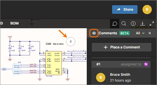
Comments are posted, replied to, and managed directly within the main viewing area using a contextual commenting window. Comments are also presented in the Comments pane on the right-hand side, which provides more of an overview/navigational instrument, rather than the operational interface.
Use the

control to toggle the display of the
Comments pane.
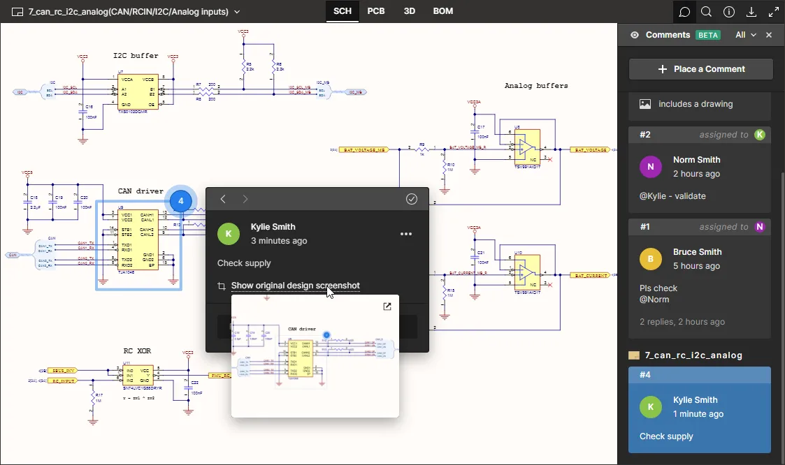
 Example comments overlayed on a child schematic sheet of a managed project. The Comments pane reflects all comments, while the accessible window in the main viewing area provides contextual commenting.
The Commenting functionality is used in the following places:
- In the Design view of the Projects Management page, when managing a specific project. Comments can be added to a schematic (SCH data view) or 2D view of the board (PCB data view). Comments made here appear automatically in the Design view of the shared live design and in Altium Designer, and vice versa.
- In the Design Snapshot view of the Manufacturing Portal, for the chosen release package of the managed project actively being inspected. Comments made here appear automatically in the Design view of the Projects Management page, the Design view of the shared live design, and in Altium Designer.
Placing a Comment
To place a comment:
- Click the
 button at the top of the Comments pane – the cursor will change to a cross-hair and you will enter comment placement mode.
- Place one of the following three supported comment types as required:
- Comment on a point – click at any point to attach (or 'pin') a comment to that point.
- Comment on object – as you move the cursor around the view, supported objects to which you can attach a comment to will be highlighted. For the SCH data view supported objects are components, pins, wires, busses, and ports. For the PCB data view, supported objects are components, pads, vias and track segments. Click on an object to attach (or 'pin') a comment to that object.
- Comment on area – click and drag to define an area to attach (or 'pin') the comment to.
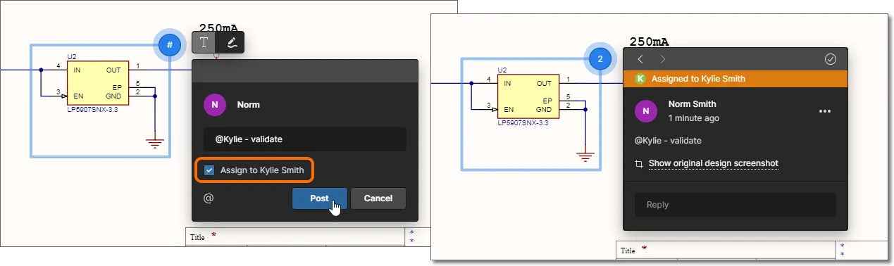
- In each case a commenting window will be presented, with which to define the comment in context with the chosen point, object, or area. Type your comment in the field provided. You can mention, using the @ character, one or more users or roles in the comment. Click the
 button to quickly access the full list of registered server members. A comment can also be assigned to a user/role. For more information on these additional features, see the section Working with the Contextual Commenting Window.
- With comment entered, any mentions added, and assignments made if required, click the
 button beneath. The comment will be committed, appearing in both the contextual commenting window and the Comments pane. A uniquely numbered marker for the comment will present in the main design viewing area.
Comment markers are unique to a project and are issued sequentially as comments are placed across that project.
At any point before posting you can exit comment placement mode by pressing Esc.
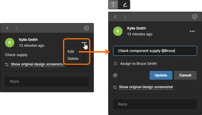
The following sequence image shows the addition of an example comment to a component, along with adding a mention of a team member (server user) and assigning that comment to them.
Comments applied in the Web Viewer interface in the following places become available in Altium Designer and vice-versa, and all changes to comments are reflected in those two places:
- In the Design view of the Projects Management page (when managing a specific project).
- In a Design Snapshot view when accessing a specific release of a project (through the Manufacturing Portal).
In Altium Designer, the
Comments panel is command-central for comments. For a high-level run-through of working with comments in relation to a managed project in Altium Designer, see
Project Commenting.
Working with the Contextual Commenting Window
The following points relate to working with comments and the interface's contextual commenting window:
- The commenting window is accessible independently of the Comments pane – click on a comment marker to access it.

If the comment marker is moved, the commenting window will move also. The window can be moved freely by itself as well.
- Use the
 buttons at the top-left of the commenting window to sequentially cycle to the previous and next comments respectively. Cycling is based on the numbering of the comment markers and will simply zoom and center the point, object, or area of the design that the previous/next comment is associated to, and present that comment in the commenting window.
- Once an initial comment has been made the commenting window, when accessed, will be ready for entry of a reply. Type your text in the field provided, then click the
 button to commit. To exit without replying, click the
  button.
- You can mention a person or role within a comment. Click the button to access a pop-up listing of all members of the server. Alternatively, search for the role or user (the latter by their name or email). Start typing '@' followed by one or more characters – a list of matching roles and users will be presented from which to choose.
- You can assign the comment to a person who has been mentioned by enabling the Assign to <name> option. If multiple people have been mentioned, a drop-down will be provided to choose which person to assign the comment to. The assigned person will be shown in a banner at the top of the window, which is simply a visual indicator to clarify who should deal with the comment – note that the assignee will see
Assigned to You in the comment banner. The assignment can be changed or removed when editing the comment.
- When adding a new comment or editing an existing one, you have the opportunity to add a freehand drawing to the design view and associate/attach it to that comment. To do so, click the
 button above the commenting window. You will enter freehand drawing mode and the commenting window will be temporarily replaced with a floating control bar. Note that you can always switch back to the 'comment' mode by clicking the
  button. In freehand drawing mode, place the cursor, and then click and drag to build the artwork you require. Buttons on the control bar allow you to change the color and width of the drawing line (helpful for the 2D view of the PCB), and if you make a mistake just click
  to delete the drawing and start again. The comment can also be posted or canceled from the control bar using the buttons at the far right.
- When a new comment is posted, a screenshot of the original view is taken and attached to that comment. From within the commenting window, this can be accessed by clicking the Show original design screenshot control. The screenshot presents exactly what was seen in the view at the time of comment creation – so same zoom level, active layers (PCB), and also includes the freehand drawing if one was created prior to posting the comment.
Click the

control at the top-right corner of the screenshot to access its full-size view. Click away from the view to return to the commenting window.
- A comment can be edited or deleted, through the commenting window only, using the Edit and Delete commands from the
 menu. Note that these commands will only be available for a comment that you yourself have made – you cannot edit or remove a comment made by another user. If you edit an existing comment, make your changes then click the
  button to commit. To exit without applying any changes, click the button.
If you delete a comment, be aware that all associated replies will also be deleted.
- When the commenting window is accessed (by clicking on its associated marker, or by selection on the Comments pane) only the initial and latest comments in the thread are presented. To see all comments in the thread, click on the available control between these entries. Use the scrollbar to browse through all comments.

- Anybody viewing the shared design project can resolve a comment. To do so, click the
 control at the top-right of the commenting window. The control will change to
  , reflecting the comments' resolved state. To unresolve – that is, make the comment active again – click the control again. In addition, the associated comment marker will become dimmed. Resolved comments can be hidden from the main viewing area through an option available on the Comments pane – see the next section for more information.
The comment marker will also change from

(unresolved) to

(resolved) for a comment that is not currently selected (the commenting window is not open for).

- If a person has made a comment while reviewing a specific release of a design project (in the Design Snapshot view of the Manufacturing Portal), then that comment will include the release information as a link to that release.

- You can add a URL link as part of your comment post – just copy the URL and paste it into the comment field. It will be detected and presented as a standard link that can be followed when clicked.

Working with the Comments Pane
The following points relate to working with comments and the interface's Comments pane:
- The Comments pane facilitates an overview/navigational tool for comments across the project, rather than the operational interface of posting, editing and replying. That functionality is solely left to the contextual commenting window.
- Use the control at the top-left of the pane to display comment markers within the main viewing window (
 ), or to hide them (
 ).
).
- At the top-right of the Comments pane is a control that gives access to filtering controls, so that you can determine what is presented in the pane.

Two levels of filtering can essentially be defined. The first, or primary level allows you to control which comments are displayed:
- All – all comments, from all users.
- My – only present comment threads that you yourself started, replied to, or have been mentioned within.
- From – only present comment threads that a specific person started, replied to, or has been mentioned within. Choose a person from the associated drop-down list, which includes all people who have actively participated in commentary for the project.
The primary filtering employed is reflected next to the drop-down control used to access the filtering controls.
The secondary level of filtering, which is applied in conjunction with the primary filtering method offers two options, allowing you to hide all resolved comment threads (Unresolved only enabled) and/or to only show comments for the active document being viewed, rather than the entire project (Current document only enabled).
- Click the Notification Settings entry (at the bottom of the filtering options window) to access a window with which to configure which comments in the project you will receive email notifications for. Choose to receive notifications for all comment threads, no comment threads, or only those you are involved in (you started, replied to, or have been mentioned within).
- In terms of ordering of comment threads in the pane, again there are two levels. Firstly, comments are ordered by the document they are on, and this follows the same ordering as the source document navigation structure in the left-hand pane. Secondly, for each document, the comments are ordered by the date of their creation – in descending order.
- As you click on a comment thread entry in the pane, that comment will be focused in the main viewing window, and opened in the contextual commenting window. The same comment marker number is reflected in the Comments pane, making it easy to see which comment you are viewing. If you click on a comment that doesn't reside on the document currently being viewed, then that document of residence will be made the active document.
- Each comment entry in the pane provides a useful summary of key information relating to that comment, as shown in the example below.

If a person has made a comment while reviewing a specific release of a design project (in the Design Snapshot view of the Manufacturing Portal), then that comment entry will include the release information as a link to that release.
Other Things to be Aware of
- If a comment is associated with an object and that object gets removed from the design, then the comment will be converted to an area comment and remain at the same coordinates. The comments' original design screenshot can prove very useful in this respect.
- If a design document is removed from the project, any comments associated to that document will be hidden.
- If an object is moved within the design, the comment associated to it will also move.
- For designs that made use of freehand comments in previous versions of Altium Designer, those will be converted to area comments, and the freehand drawing attached to the comment in each case.
- Versions 20.x of Altium Designer will ignore line color and width settings used in the freehand drawings. Instead, such drawings will appear using red colored lines only and using the standard, non-adjustable line width available for comments in those earlier versions of the software.
- A resolved comment cannot be deleted. You would need to make it unresolved and then delete.
Updating with New Data
When using the Web Viewer interface to inspect the documents of the latest source project – from the Design view of the Projects Management page (when managing a specific project), or when viewing a shared live design – the data will update automatically whenever the project is committed back to Concord Pro (from Altium Designer). Notification will appear within the interface shortly after the committal. Once the new data has been generated, click the  control to update the view with that latest data set.
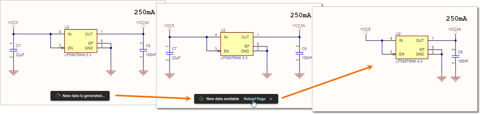
If you make changes to the design and commit to the server from within Altium Designer, then the Web Viewer interface will automatically detect and make the new data available.
