
KB: Creating user-defined component classes and rooms directly from the schematic
Solution Details
When you need grouping beyond sheet-based generation
During schematic-to-PCB synchronization, Altium Designer can automatically generate component classes and rooms, commonly based on schematic sheets. In many designs, there is a requirement to group only a specific subset of components on a sheet, such as a power section or interface block, into a dedicated component class and corresponding room rather than grouping all components on the sheet.
How schematic definitions become PCB classes and rooms
User-defined component classes created in the schematic using directives or component parameters are not created immediately in the PCB. Instead, they are detected and transferred to the PCB during schematic-to-PCB synchronization (ECO). Component classes are created or updated in the PCB based on these definitions. Room objects themselves are PCB editor objects; when room generation is enabled, rooms are generated during synchronization and then managed in the PCB editor.
Choose a directive-based or parameter-based approach
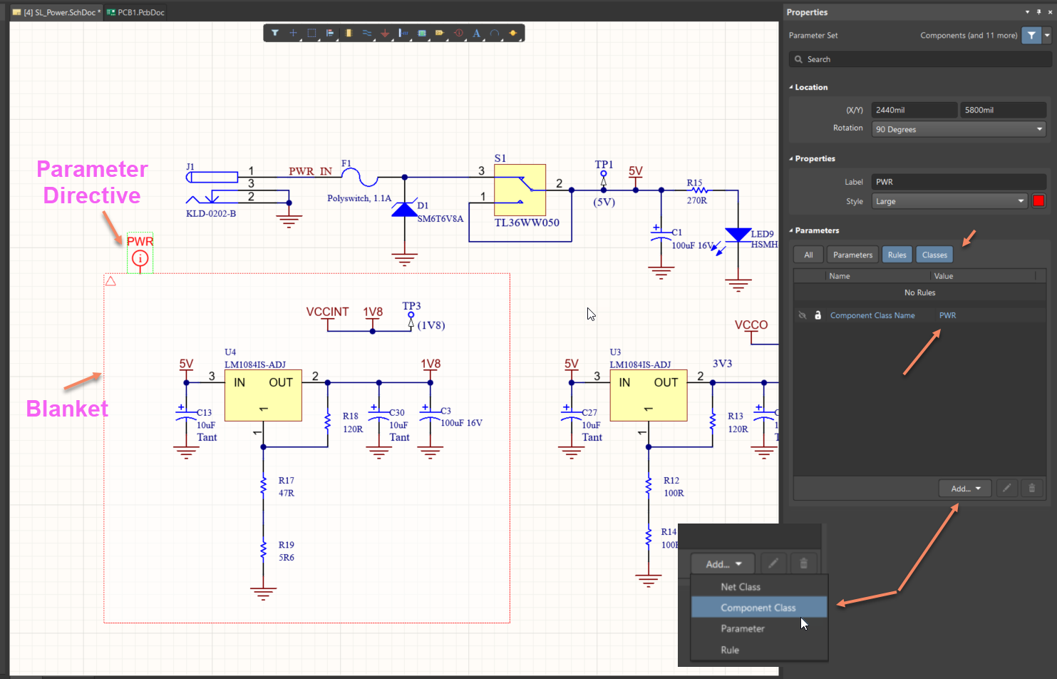
- Directive-based grouping: Use a Blanket directive to scope a group of components, then apply a Parameter Set directive that adds a Component Class parameter to define the class for that group.
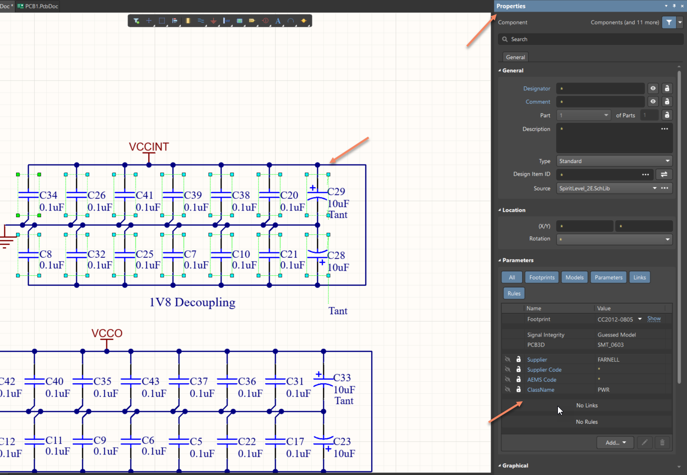
- Parameter-based grouping: Add a component parameter named ClassName to each component that should belong to the class.
Schematic-defined component classes can be used with either traditional PCB Design Rules or the Constraint Manager, depending on the constraint-definition workflow selected when the project was created.
Step-by-step schematic configuration
Directive-based grouping:
- Open the schematic sheet and identify the group of components to be grouped (for example, a power section).
- Select Place » Directives » Blanket and draw the blanket around the required components.
- Select Place » Directives » Parameter Set and place it on the blanket outline so it is logically associated with the blanket. Ensure the Parameter Set crosshair touches the blanket boundary to ensure correct scoping.
- With the Parameter Set selected, open the Properties panel and optionally set a name (for example, PWR).
- Click Add, choose Component Class, and set the value to the desired class name (for example, PWR).
- All components within the blanket will be assigned to this user-defined component class during ECO synchronization.
Parameter-based grouping:
- Select a component on the schematic.
- Open its Properties panel.
- Under Component Parameters, click Add.
- Add a parameter named ClassName and set the value to the desired component class name (for example, PWR).
- Repeat this for each component that should belong to the same component class.
Important: The value of the ClassName parameter must exactly match the intended component class name, including spelling and case, to ensure correct class creation or merging during synchronization.
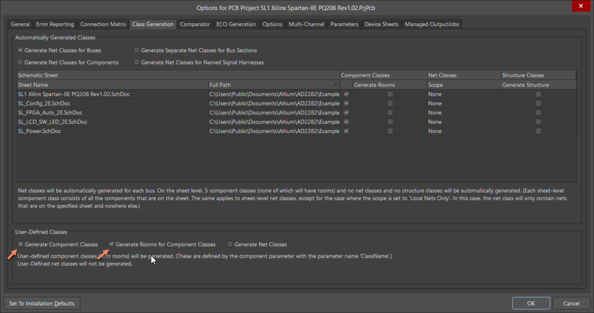
Enable component class and room generation
- Go to Project » Project Options.
- Open the Class Generation section.
- Enable Generate Component Classes.
- Enable Generate Rooms for Component Classes.
- Click OK and run schematic-to-PCB synchronization (ECO).
Additional Notes
- The ClassName component parameter is a local parameter and may be overwritten when updating components from libraries, depending on update settings.
- To preserve schematic-defined class assignments, use the option to replace selected attributes for symbols on sheets and exclude the locally defined ClassName parameter during component updates.
- Although rooms can be generated from schematic-defined component classes during ECO, room creation and editing is performed in the PCB editor.