KB: Specify via style during interactive routing
Solution Details
By default, via size during interactive routing is determined by Routing Via Style rule specified on a given *.pcbdoc, but if you insist, it could be changed to User Choice in Preferences, PCB Editor - Interactive Routing, under Interactive Routing Width Sources, on Via Size Mode pulldown.
There is also a keyboard shortcut '4' to cycle through the modes on the fly. The User Choice can be changed further by Shift+V keyboard shortcut. Please refer our online manual for further details:
Changing the Via Size Mode While Routing
Obviously, prescribing via definition upfront is a more recommended practice, and if it needs to be managed/reused across multiple designs within your team, it is best to manage it in a form of *.pvlib Pad Via template library from which each *.pcbdoc can reference in its rule.
There is also a separate default setting in Preferences, PCB Editor - Defaults , Via located under Primitive List, which only applies during a standalone Place » Via menu command, and NOT on a via placed during interactive routing.
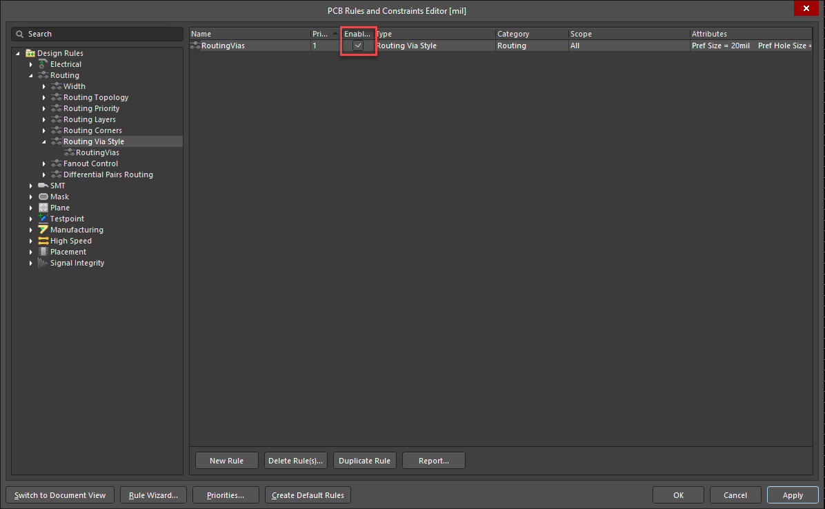
In a given *.pcbdoc, you can access the Routing Via Style rule by going to: Design » Rules » Design Rules » Interactive Routing » Routing Via Style.
Make sure that a Routing Via Style rule with the desired size is created and enabled the Routing Via Style rule in the PCB Rules and Constraints Editor.