
KB: 유연한 PCB의 구부림을 구성하고 애니메이션하기
Solution Details
To animate the bending of a PCB that is entirely flexiible in 3D mode, at least one stationary Rigid board region is required to be used as a frame of reference. Conveniently, in a typical design, there is a small portion at an end of the board which interfaces with another board that needs to be strengthened mechanically, say, by glueing a stiffener, that may be assigned to this Rigid board region.
1 In Layer Stack Manager or Design » Layer Stack Manager, create two identical sub-stacks, differing only by one with 'Is Flex' option enabled (Flex) and the other disabled (Rigid). 
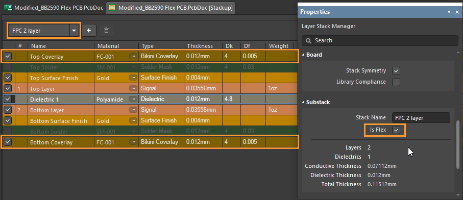
When making use of custom bikini coverlays your sub-stacks will not be identical though custom overlays in the Flex sub-stack will equal the standard solder mask layers in the Rigid sub-Ssack per the 3D output.
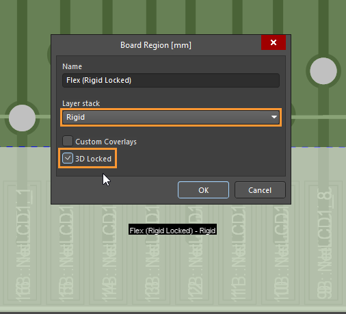
2 In Board Planning Mode or View » Board Planning Mode, define the small board region at an end to be used as a frame of reference.
3 Double-click on the board region in Step 2 and assign the Rigid sub-stack from Step 1 with '3D Locked' option ticked.
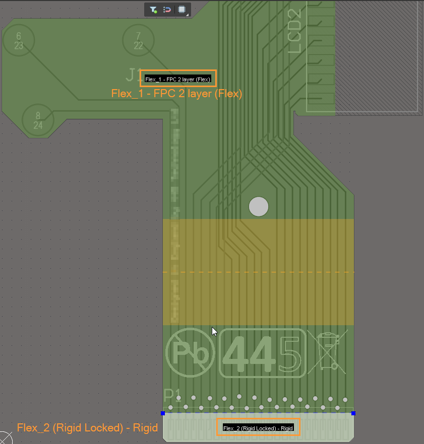
4 Double-click on the main Flex region and define and configure bending lines.
5 In 3D mode or View » 3D Layout Mode, hit '5' to verify the bending angle/orientation in 3D mode. 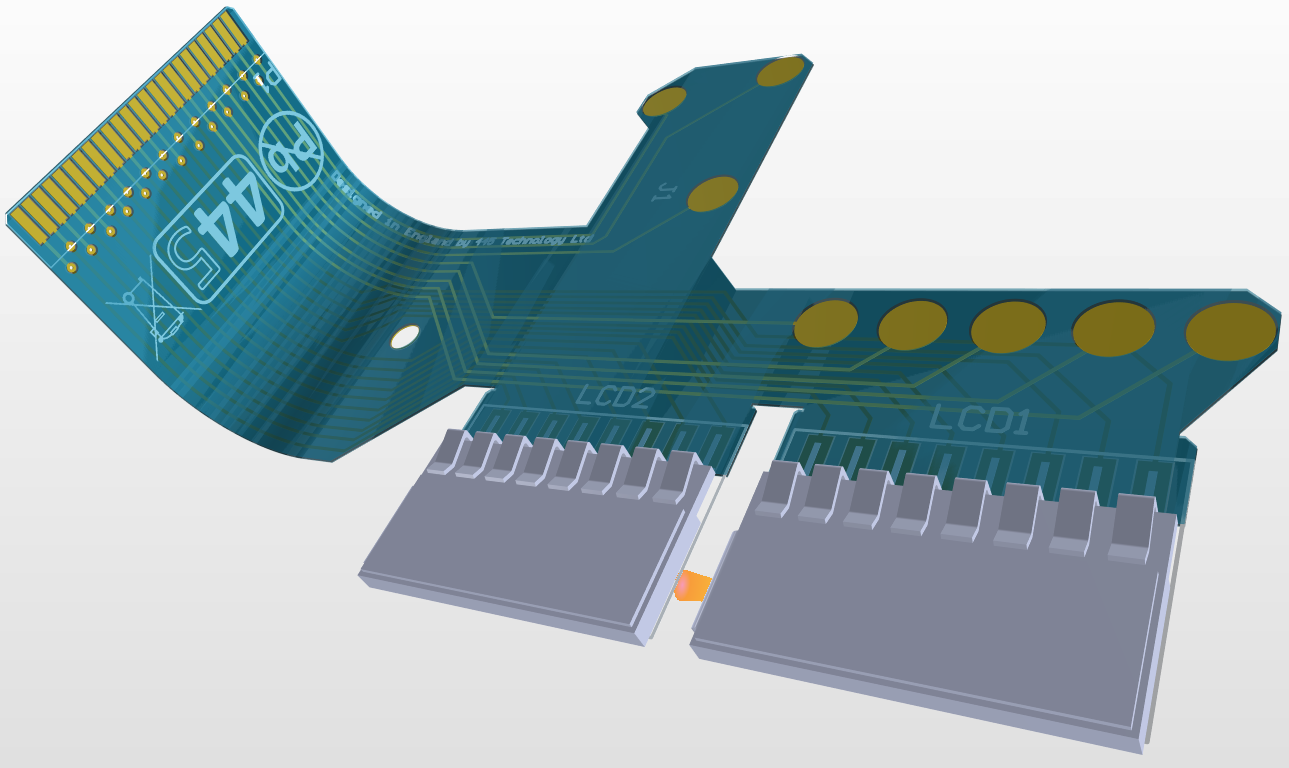
Please refer our online manual for further details:
Defining the Layer Stack
Defining Board Regions & Bending Lines