
BOM Management with ActiveBOM
ActiveBOM is a powerful Bill of Materials (BOM) management editor that combines comprehensive BOM management tools with Altium's powerful part-information aggregation technologies, helping you manage the component selection challenge and providing you with instant visibility to component availability and potential supply chain risks.

The ActiveBOM document is the master list of all items needed to build the board.
ActiveBOM is the component management editor included in Altium Designer, which is used to:
-
Configure the component information so that it is BOM-ready, including adding additional non-PCB component BOM items, such as the bare board, glue, mounting hardware, and so on.
-
Add additional columns, such as a line number column, to suit the requirements of the assembly house.
-
Map each design component to a real-world manufacturer part.
-
Verify the supply chain availability and price for each part, for a defined number of manufactured units.
-
Calculate the cost to build for the defined number of manufactured units.
This ability to inject supply chain details directly into the BOM changes the role of the BOM document in the PCB project. No longer a simple output file, ActiveBOM raises the component management process to sit alongside the schematic capture and PCB design processes, where ActiveBOM's BomDoc becomes the source of all Bill Of Materials data for the PCB project for all BOM-type outputs. ActiveBOM is the recommended approach to BOM management.
Setting Up an ActiveBOM Document
To create a new ActiveBOM document for your design project, right-click the project's entry in the Projects panel and select Add New to Project » ActiveBOM command from the context menu. The ActiveBOM document listing all of the components in the design will open in the design space.

A newly created ActiveBOM document will be the active document in the design space.
Options for an ActiveBOM document are configured in the Properties panel. The main options are configured on the General tab of the panel:
- Production quantity and preferred currency (the General region) – define the number of boards to be built (Production Quantity) and the preferred Currency to display component prices. The production quantity value is used during supply chain searching to check component availability from the suppliers.
-
Supply chain options (the Supply Chain region) – define the number of manufacturer parts you would like to be located for each BOM item (Solutions per Item) and the number of suppliers you would like to be located for each manufacturer part (Suppliers per Solution).
From here, you can also exclude all supplier part numbers considered invalid (no stock, no prices available, or out-of-date price/availability – Exclude Invalid SPNs) and define the overall list of suppliers for the ActiveBom document (Favorite Suppliers List).

Configure options of the ActiveBOM document in the Properties panel.
The BOM item list of the ActiveBOM document shows both item details and supply chain information (for the entered numbers of manufacturers and suppliers).

BOM item details and supply chain information are shown in the ActiveBOM document.
Data columns shown in the BOM item list of the ActiveBOM document are configured on the Columns tab of the Properties panel. Use the visibility icons in the column list to define their visibility.

Configure visibility of data columns as required in the Properties panel.
Line numbers of BOM items are defined in the Line # column. You can automatically set the line numbers by clicking the ![]() button at the top of the ActiveBOM document.
button at the top of the ActiveBOM document.

Set line numbers for BOM items automatically using the Set line numbers feature.
Working with Solutions
Each manufacturer part for a BOM item in the ActiveBOM document and available suppliers of this manufacturer part is referred to as a Solution for this item. In the row for each solution, the manufacturer part is detailed on the left, with each available supplier detailed on a separate color-coded tile.

A solution couples the design component to the manufacturer part and the available suppliers.
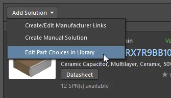
For a component placed in your design from the Workspace Library, each Part Choice defined for this component automatically presents as a solution in the ActiveBOM document. You can edit part choices for the selected Workspace Library component by clicking the Add Solution button at the top of the solution region of the ActiveBOM document and selecting the Edit Part Choices in Library command from the menu that appears.
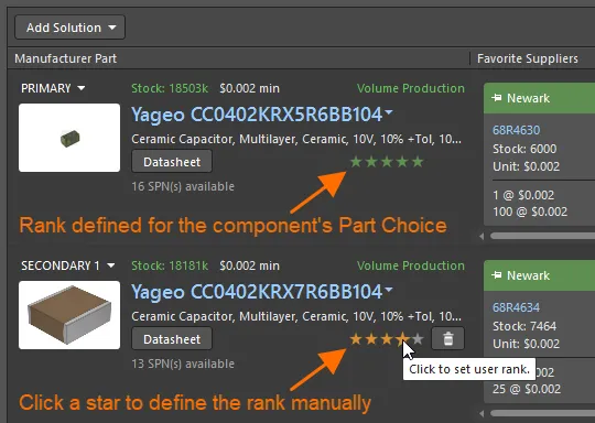
For components with multiple solutions, the solutions are automatically ranked from highest to lowest based on the part's availability, price and manufacturer lifecycle state. If you prefer to use a lower-ranked solution, you can override the automatic ranking by defining a user rank using the star feature. For Workspace Library components, you can also rank its part choices, and this ranking will be reflected in the ActiveBOM document.
Verifying the BOM
Each BOM item is checked for violations, and its status is displayed in the BOM status column, which is always visible on the right side of the BOM items list. An icon indicates the item's status: clear (no issues), warning, error, or fatal error. Hover the cursor over an icon to see details about issues detected for this item.

Explore the BOM status column for detected BOM item violations.
The list of violations currently present in the ActiveBOM document and the number of items offended by each violation type is displayed in the BOM Checks region of the General tab of the Properties panel.

The BOM Checks region of the Properties panel summarizes violations detected in the ActiveBOM document.
Click the ![]() button at the bottom of the region to access the BOM Checks dialog from where you can configure the severity level (report mode) of each BOM check.
button at the bottom of the region to access the BOM Checks dialog from where you can configure the severity level (report mode) of each BOM check.

Configure report modes for violation checks in the ActiveBOM document using the BOM Checks dialog.