
Analyzing Your Design Using Circuit Simulation
At a Glance
- Learn why simulation is valuable for checking circuit behavior, adjusting designs, and making measurements that may be difficult or impractical on the bench.
- See how Altium Designer supports SPICE-based mixed-signal simulation, including analog, digital, and mixed analog-to-digital circuits.
- Get a view of the simulation process in Altium Designer, plus a guided example that shows how to prepare a schematic and begin running analyses.
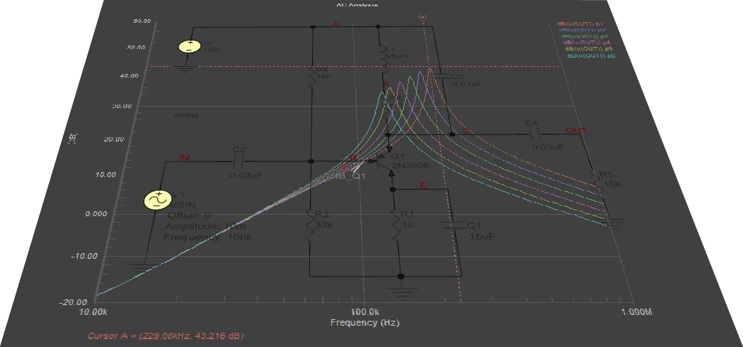
Circuit simulation allows you to explore your ideas before committing to manufacture. Concepts can be verified, and the circuit can be tuned quickly and accurately. Circuit simulation also gives you the opportunity to perform measurements that may not be physically possible on the workbench.
The main purpose of simulating the function of an electronic device is to represent and analyze the performance of the design. It is impossible to imagine the design of even the simplest device without the capabilities that simulation offers. Using simulation software makes it possible to analyze all modes of the device being designed without possible damage, to determine parameters and characteristics that are difficult to measure in real conditions, and to perform measurements that might otherwise require the use of expensive measurement equipment.
SPICE (Simulation Program with Integrated Circuit Emphasis) was developed as an open-source software package, which has led to its broad popularity and continued development. Altium Designer's Mixed Simulation (MixedSim) technology uses an improved core based on SPICE algorithms and is designed to simulate analog, digital or mixed analog-to-digital device electrical circuits. It is a true mixed-signal simulator, meaning that it can analyze circuits that include both analog and digital devices. It is fully SPICE3f5 compatible, as well as providing support for a range of PSpice® and LTspice® device models.
The simulation process in Altium Designer can be split into the following stages:
- Verifying & Preparing a Project for Simulation – the design to be simulated should be verified and adequately prepared so you can receive the proper simulation results. This includes placing components with simulations models, setting signal sources and defining points of interest in the circuit using probes. The verification process gives feedback if something is wrong with the schematic to be analyzed.
- Configuring & Running a Simulation – simulations are performed directly from the schematic and can also be re-run as you analyze the simulation waveforms. Quickly configure the required analysis type and the output expressions to be plotted, then run the simulation.
- Working with Simulation Results – simulation results are displayed in the SimData editor. This is a feature-rich environment where you can quickly and efficiently analyze simulation results, enabling you to assess, debug and ultimately emerge confident in the operation of your design.
Mixed Simulation – Example Guide
The collapsible section below takes you through the process of creating a simulation-ready schematic of a filter circuit, which is then used to run some circuit simulation analyses.
Creating a New Design Project
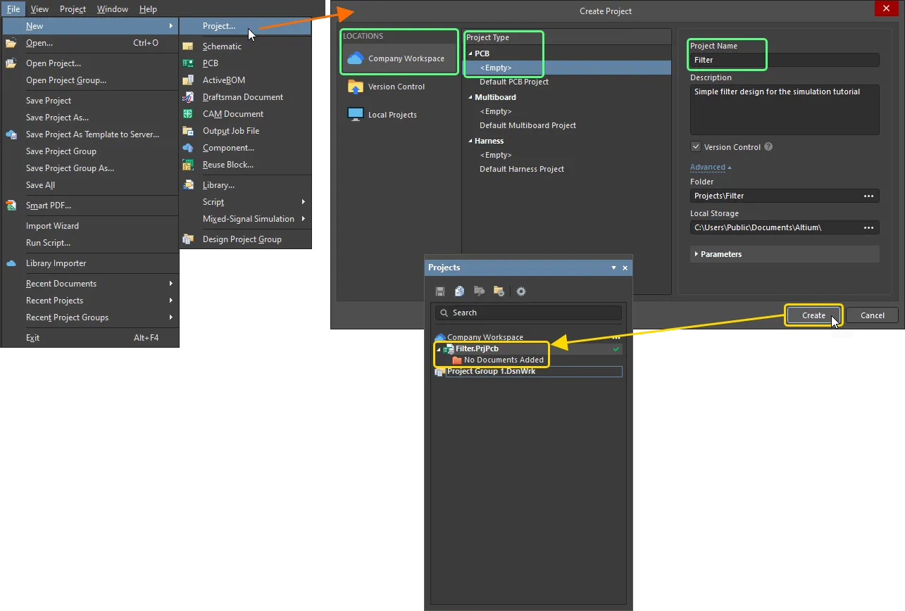
- Select the File » New » Project command from the main menus.
-
The Create Project dialog will open:
- In the Locations list, select the entry for your Workspace (or the Local Projects entry if you are not using a Workspace).
- In the Project Type list, choose the <Empty> entry under the PCB type.
-
Enter
Filterin the Project Name field. - Set other options on the right-hand side of the dialog as required (e.g., the storage folder) and click the Create button.
A new project will be created, and the project entry will appear in the Projects panel.
-
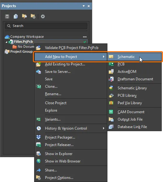
Right-click the project entry in the Projects panel and select the Add New to Project » Schematic command from the context menu.
-
A blank sheet of a new schematic document will appear. Save it on your hard drive by right-clicking its entry in the Projects panel and selecting the Save As command from the context menu. The Save As dialog will open, ready to save the document in the same location as the project file. Type
Filterin the File name field and click Save (there is no need to type in the extension, as it will be added automatically). - Since you added a new document to the project, the project file has changed. Right-click on the project entry in the Projects panel, then select Save to save the project changes.
Capturing the Circuit
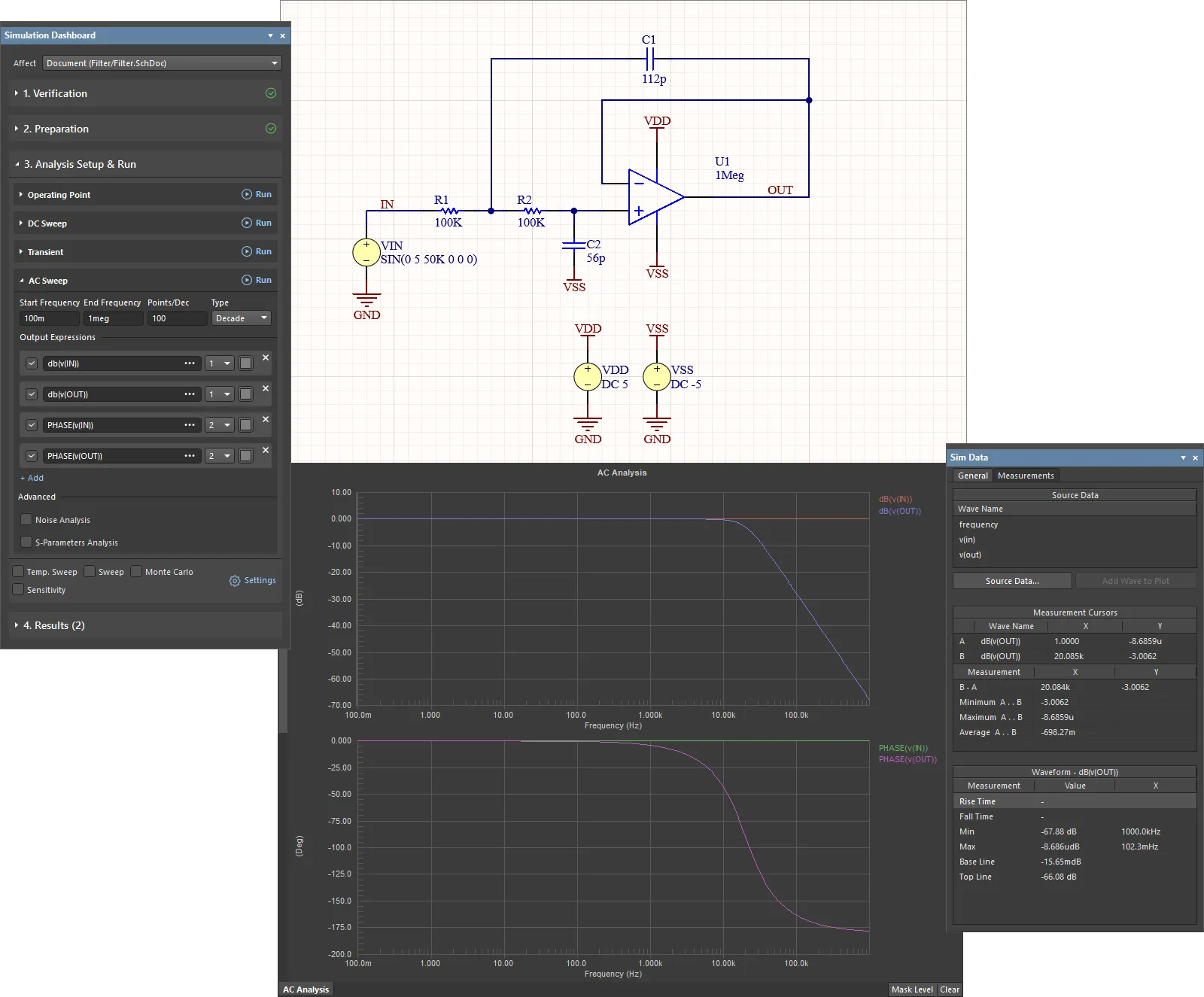
The filter circuit to be simulated is shown below. In this section, we will locate the required components, set up their component properties and then wire the schematic.
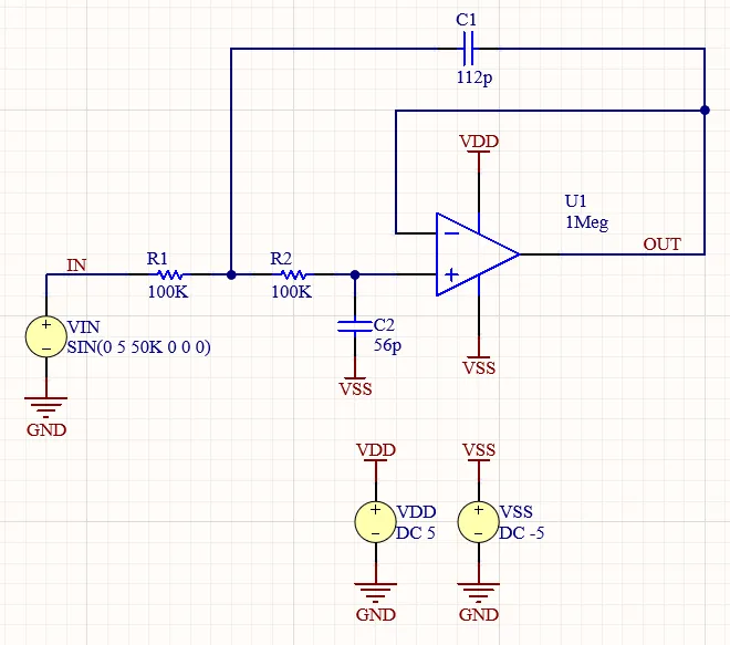
Schematic of the filter circuit
Placing Simulation-Ready Components
-
Components for the schematic will be sourced from the
Simulation Generic Componentslibrary provided with an Altium Designer installation by default:-
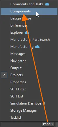
Open the Components panel by clicking the Panels button at the bottom-right of the design space and selecting Components from the menu that appears.
-
Select the
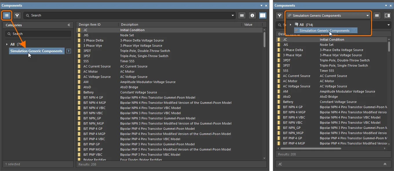
Simulation Generic Componentslibrary from the drop-down at the top of the panel (if the panel is in its compact mode) or from the Categories pane access by clicking the button at the top-left of the panel (if the panel is in its normal mode). The list of components the library provides will be presented in the panel.
-
-
Place the operational amplifier:
-
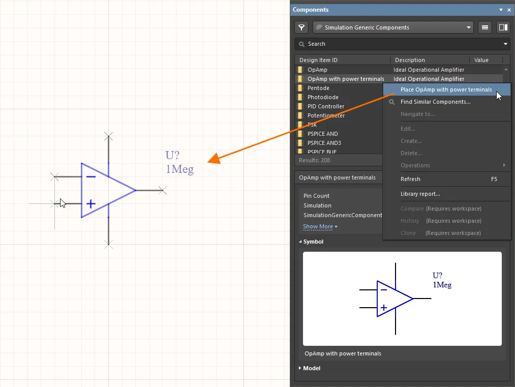
In the component list, find the OpAmp with power terminals component, right-click its entry and select the Place command from the main menus. The component will appear attached to the cursor in the design space but do not place the component yet.
- While the op amp is floating on the cursor, press the Tab key to open the Properties panel, where you can edit its properties before placing the component on the schematic.
-
In the General region of the Properties panel, change the Designator to
U1.
-
Click the Pause button (
 ) in the design space to return to component placement.
- Click in the design space to place an instance of the op amp.
- You will stay in component placement mode to place further component instances. Since only one instance of the op amp component is required for this circuit, right-click to exit component placement mode.
-
-
Place resistors:
- In the Components panel, find the Resistor component, right-click its entry and select the Place command from the main menus.
- While the resistor is floating on the cursor, press the Tab key.
-
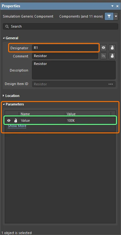
Change the component properties in the Properties panel that opens as follows:
-
In the General region, change the Designator to
R1. -
In the Parameters region, change the Value of the
Valueparameter to100K.
-
In the General region, change the Designator to
-
Click the Pause button () in the design space to return to component placement.
-
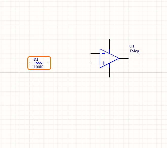
Click in the design space to place an instance of the resistor.
-
Move the cursor and click in the design space to place another instance of the resistor with the same value. The designator of the new instance will be incremented automatically (
R2).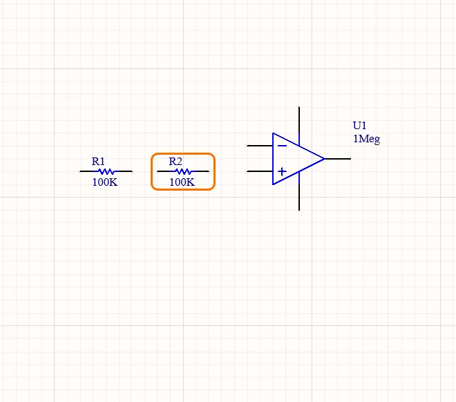
- Right-click to exit component placement mode.
-
Place capacitors:
- In the Components panel, find the Capacitor component, right-click its entry and select the Place command from the main menus.
- While the capacitor is floating on the cursor, press the Tab key.
-
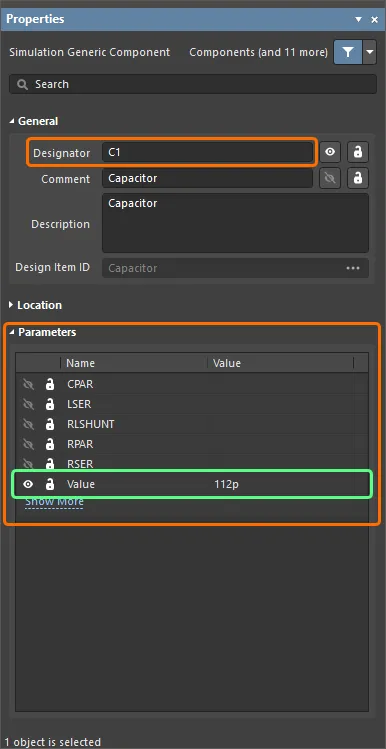
Change the component properties in the Properties panel that opens as follows:
-
In the General region, change the Designator to
C1. -
In the Parameters region, change the Value of the
Valueparameter to112p.
-
In the General region, change the Designator to
-
Click the Pause button () in the design space to return to component placement.
-
Click in the design space to place an instance of the capacitor.
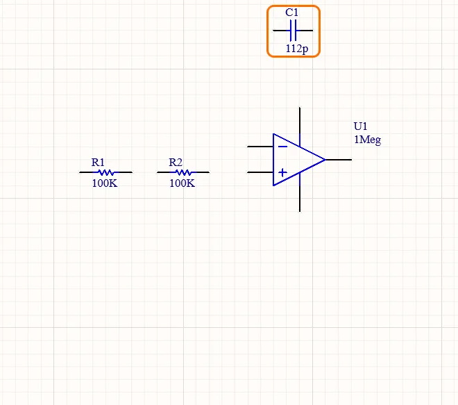
- While the capacitor is still floating on the cursor, ready to place another instance of the capacitor, press the Tab key.
-
In the Parameters region of the Properties panel, change the Value of the
Valueparameter to56p. -
Click the Pause button () in the design space to return to component placement.
- Press the Spacebar to rotate the component in 90° increments until it has the correct orientation.
-
Move the cursor and click in the design space to place another instance of the capacitor. The designator of the new instance will be incremented automatically (
C2).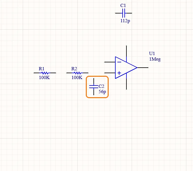
- Right-click to exit component placement mode.
Adding the Voltage Sources
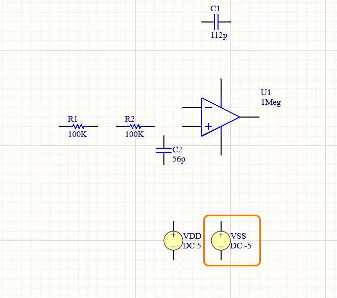
To power the circuit when simulating, voltage sources are needed.
-
Place the VDD voltage source:
- Select the Simulate » Place Sources » Voltage Source command from the main menus.
- While the voltage source is floating on the cursor, press the Tab key.
-
Change the source properties in the Properties panel that opens as follows:
-
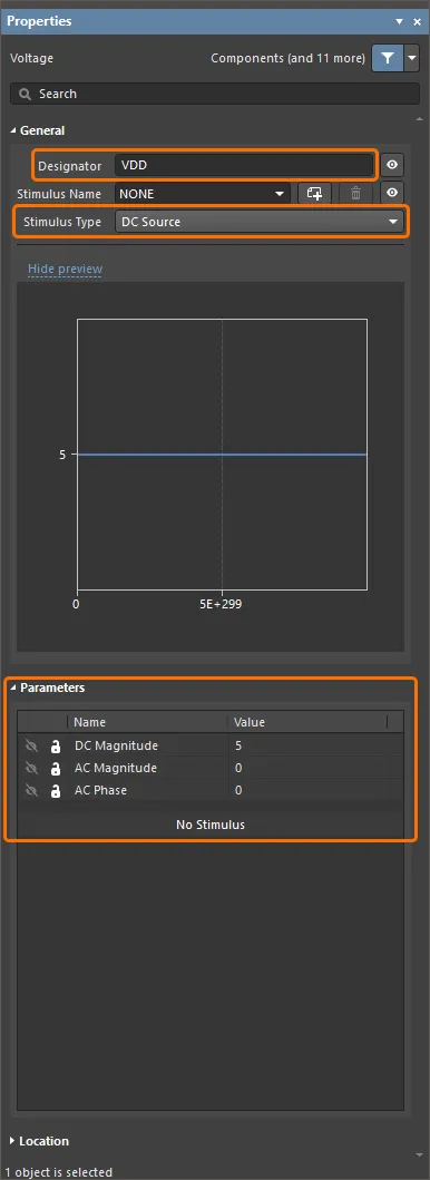
In the General region, change the Designator to
VDDand select DC Source as the source's Stimulus Type. -
In the Parameters region, change parameter values as follows:
DC Magnitude=5
AC Magnitude=0
AC Phase=0
-
In the General region, change the Designator to
-
Click the Pause button () in the design space to return to voltage source placement.
-
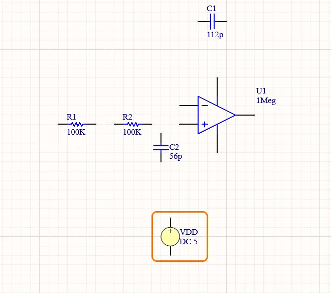
Click in the design space to place an instance of the voltage source.
-
Place the VSS voltage source:
- While the voltage source is still floating on the cursor, ready to place another instance of the source, press the Tab key.
-
Change the source properties in the Properties panel that opens as follows:
-
In the General region, change the Designator to
VSSand select DC Source as the source's Stimulus Type. -
In the Parameters region, change parameter values as follows:
DC Magnitude=-5
AC Magnitude=0
AC Phase=0

-
In the General region, change the Designator to
-
Click the Pause button () in the design space to return to voltage source placement.
-
Move the cursor and click in the design space to place another instance of the voltage source.
-
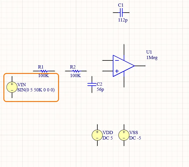
Place the sinusoidal voltage source:
- While the voltage source is still floating on the cursor, ready to place another instance of the source, press the Tab key.
-
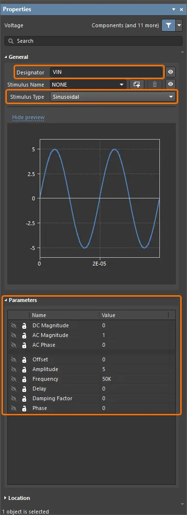
Change the source properties in the Properties panel that opens as follows:
-
In the General region of the Properties panel, change the Designator to
VINand select Sinusoidal as the source's Stimulus Type. -
In the Parameters region of the Properties panel, change parameter values as follows:
DC Magnitude=0
AC Magnitude=1
AC Phase=0
Offset=0
Amplitude=5
Frequency=50K
Delay=0
Dampling Factor=0
Phase=0
-
In the General region of the Properties panel, change the Designator to
-
Click the Pause button () in the design space to return to voltage source placement.
-
Move the cursor and click in the design space to place another instance of the voltage source.
- Right-click to exit component placement mode.
Wiring Up the Circuit
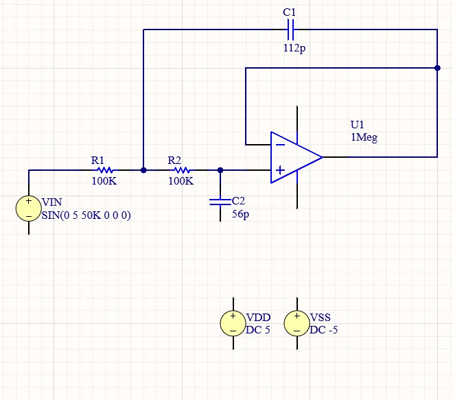
Wiring is the process of creating connectivity between the various components of your circuit. In this section, the circuit will be wired up according to the image below.
- Select the Place » Wire command from the main menus.
- Position the cursor over the hotspot of the "+" pin of the op amp – a red connection marker (red cross) will appear at the cursor location. This indicates that the cursor is over a valid electrical connection point on the component.
- Click to anchor the starting point for the wire.
-
Position the cursor over the hotspot of the nearest pin of
R2until you see the cursor change to a red connection marker. - Click to connect the wire to the pin. The cursor will release from that wire.
- Wire up the rest of your circuit, as shown in the video below.
- When you have finished placing all the wires, right-click to exit placement mode.
Adding Power Ports
-
Place GND power ports:
- Select the Place » Power Port command from the main menus.
- While the power port is floating on the cursor, press the Tab key.
-
In the Properties region of the Properties panel, set Name =
GNDand Style = Power Ground.
-
Click the Pause button () in the design space to return to power port placement.
-
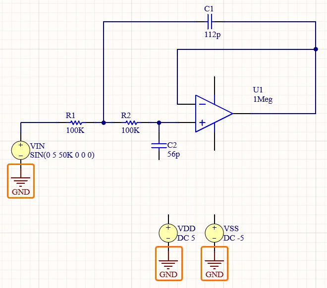
Place three power ports, one on each of the "-" pins of the voltage source components, as shown in the image below.
-
Place VDD power ports:
-
While the power port is floating on the cursor, press the Tab key and set Name =
VDDand Style = Bar in the Properties panel. -
Click the Pause button () in the design space to return to power port placement.
-
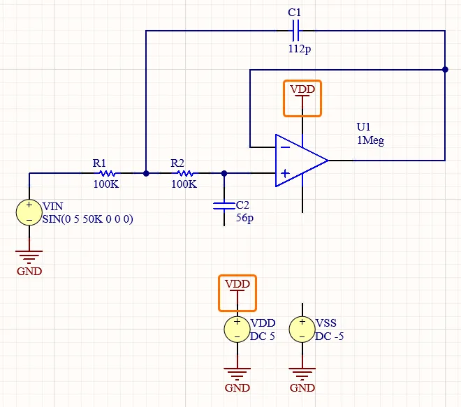
Place two power ports, as shown in the image below.
-
While the power port is floating on the cursor, press the Tab key and set Name =
-
Place VSS power ports:
-
While the power port is floating on the cursor, press the Tab key and set Name =
VSSand Style = Bar in the Properties panel. -
Click the Pause button () in the design space to return to power port placement.
-
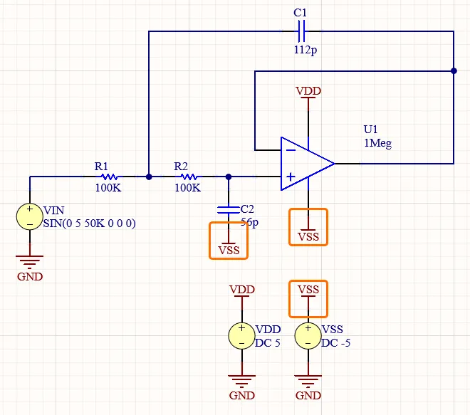
Place three power ports, as shown in the image below.
- Right-click to exit placement mode.
-
While the power port is floating on the cursor, press the Tab key and set Name =
Adding Net Labels
-
Place a net label for the input net:
- Select the Place » Net Label command from the main menus.
-
While the power port is floating on the cursor, press the Tab key and set Net Name =
IN.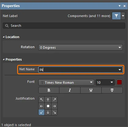
-
Click the Pause button () in the design space to return to net label placement.
-
Click to place the net label on the wire between
VINandR1. Note that the bottom left corner of the net label is its hotspot – this point must touch the wire.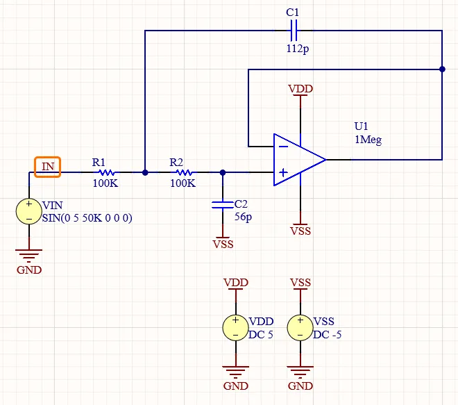
-
Place a net label for the output net:
-
While the power port is floating on the cursor, press the Tab key and set Net Name =
OUT. -
Click to place the net label on the wire exiting the output pin of the op amp.
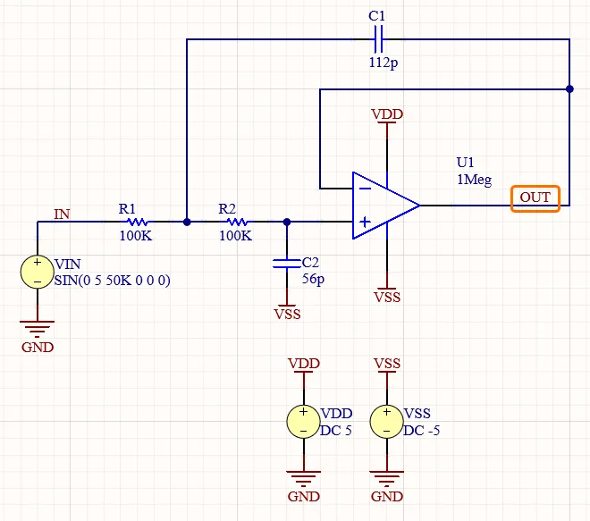
- Right-click to exit placement mode.
-
While the power port is floating on the cursor, press the Tab key and set Net Name =
- Save the schematic document by right-clicking its entry in the Projects panel and selecting Save from the context menu.
Preparing the Project for Simulation
Altium Designer allows you to run circuit simulations directly from the schematic. The simulations are configured and driven from the Simulation Dashboard panel.
- Open the Simulation Dashboard panel by clicking the Panels button at the bottom-right of the design space and selecting Simulation Dashboard from the menu that appears.
-
Expand the Verification collapsible region of the panel and click the Start Verification button. A green check should appear for both Electrical Rule Check and Simulation Models entries in the region.
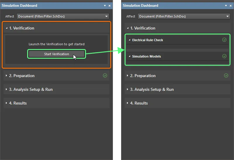
- If any violations are detected, find and fix violation conditions to continue.
-
Expand the Preparation collapsible region of the panel and make sure that all three voltage sources added to the schematic are shown in the Simulation Sources list and enabled.
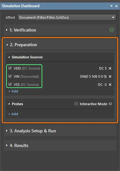
Configuring the Analyses
Setting Up a Transient Analysis
A transient analysis generates output like that normally shown on an oscilloscope, computing the transient output variables (voltage, current, or power) as a function of time over the user-specified time interval.
-
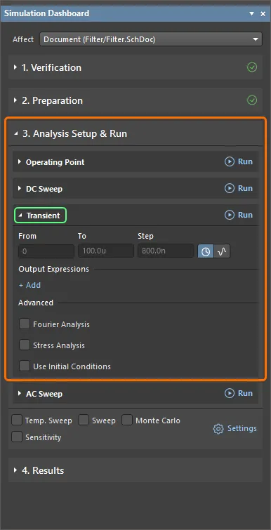
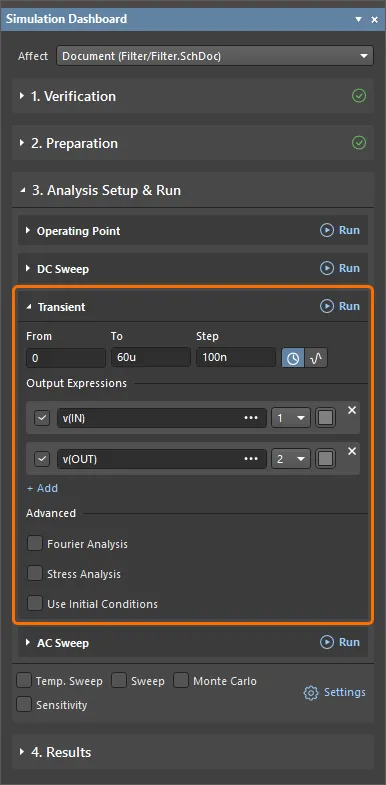
Expand the Analysis Setup & Run collapsible region of the Simulation Dashboard panel and the Transient region therein.
-
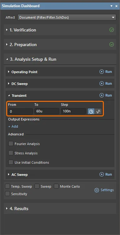
Make sure that the Interval option is selected (
 ) and enter the following values:
-
From =
0 -
To =
60u -
Step =
100n
-
From =
-
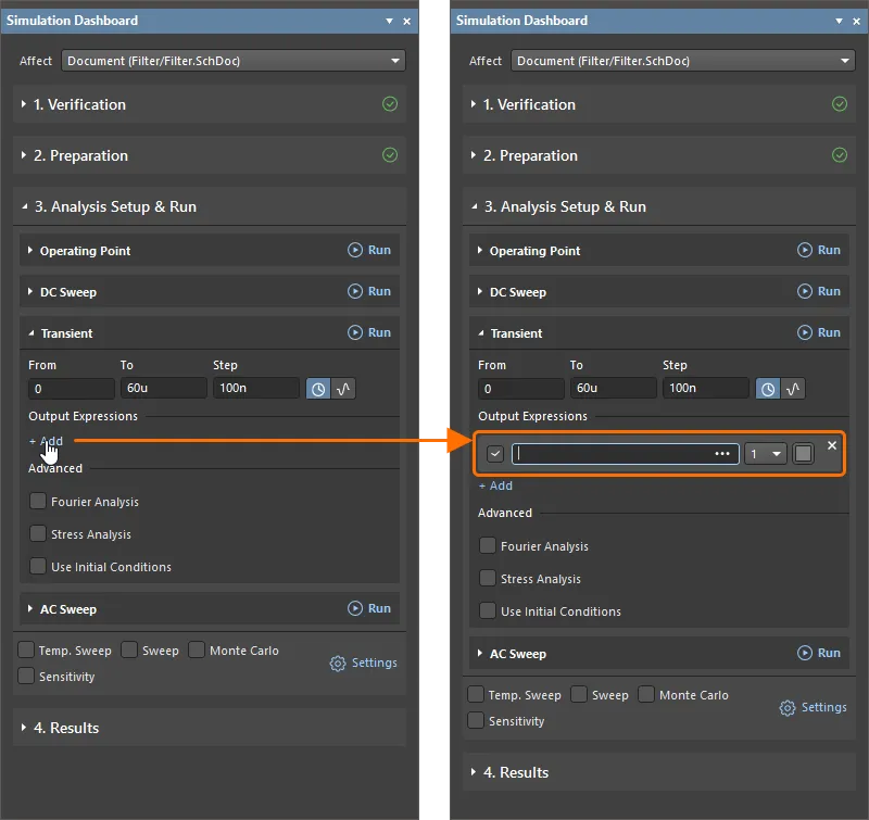
Add a new expression for the input signal. This expression will be outputted as a waveform in the simulation result document:
-
Click the Add control under the Output Expressions header to add a field for a new expression to be outputted as a waveform in the simulation result document.
-
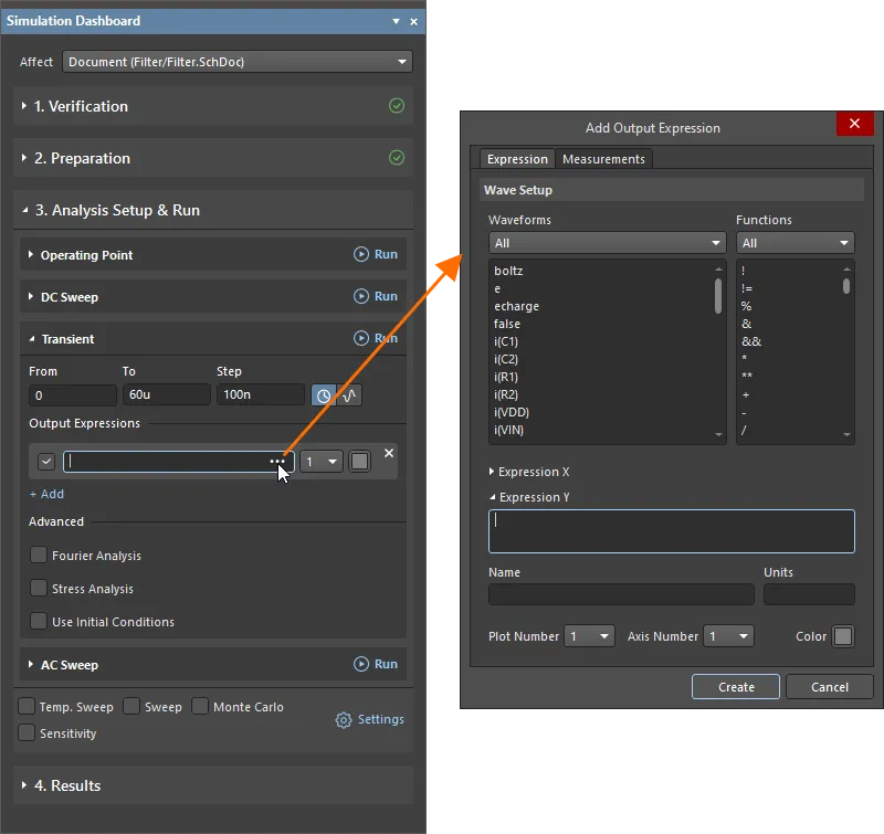
Click the
 button at the right of the added field to access the Add Output Expression dialog, where the output expression can be configured.
-
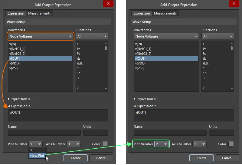
In the Add Output Expression dialog, select Node Voltages from the drop-down in the Waveform region and click the v(IN) entry in the list below. The
v(IN)expression will be added to the Expression Y field of the dialog. -
Click Create in the Add Output Expression dialog. The expression will appear in the Simulation Dashboard panel.

-
-
Add an output expression for the output signal:
-
Click the Add control in the Simulation Dashboard panel to add a field for another output expression and then the button at the right of the added field.
- In the Add Output Expression dialog, select Node Voltages from the drop-down in the Waveform region and click the v(OUT) entry in the list below.
-
Select New Plot in the Plot Number drop-down to draw the waveform for this expression in another plot in the simulation result document. After selecting, the drop-down will show 2.
- Click Create in the Add Output Expression dialog to add the expression to the Simulation Dashboard panel.
-
Click the Add control in the Simulation Dashboard panel to add a field for another output expression and then the
-
At this point, the transient analysis is configured. Its options should look in the Simulation Dashboard panel as shown below.
Setting Up an AC Sweep Analysis
An AC sweep analysis generates output that shows the frequency response of the circuit, calculating the small-signal AC output variables as a function of frequency. The desired output of an AC small-signal analysis is usually a transfer function, e.g., voltage gain.
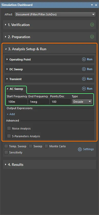
- In the Simulation Dashboard panel, expand the AC Sweep region within the Analysis Setup & Run collapsible region.
-
Select Decade as the sweep Type and enter the following values:
-
Start Frequency =
100m -
End Frequency =
1meg -
Points/Dec =
100
-
Start Frequency =
-
Add an output expression for the magnitude in decibels of the input signal:
-
Click the Add control under the Output Expressions header to add a field for a new expression and then the button at the right of the added field.
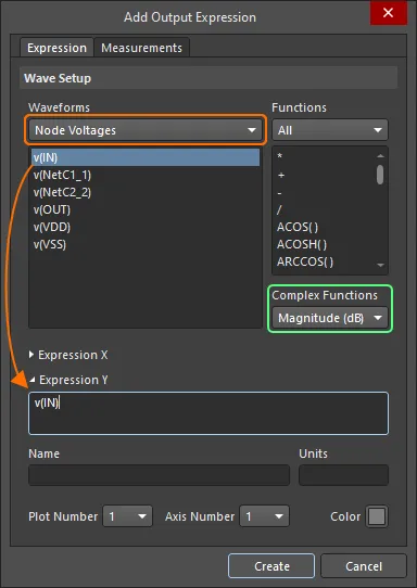
- In the Add Output Expression dialog, select Node Voltages from the drop-down in the Waveform region and click the v(IN) entry in the list below.
- Select Magnitude (dB) from the Complex Functions drop-down in the Add Output Expression dialog and click Create.
-
Click the Add control under the Output Expressions header to add a field for a new expression and then the
-
Add an output expression for the magnitude in decibels of the output signal:
-
Click the Add control under the Output Expressions header to add a field for a new expression and then the button at the right of the added field.
- In the Add Output Expression dialog, select Node Voltages from the drop-down in the Waveform region and click the v(OUT) entry in the list below.
- Select Magnitude (dB) from the Complex Functions drop-down in the Add Output Expression dialog and click Create.
-
Click the Add control under the Output Expressions header to add a field for a new expression and then the
-
Add an output expression for the phase in degrees of the input signal:
-
Click the Add control in the Simulation Dashboard panel to add a field for another output expression and the button at the right of the added field.
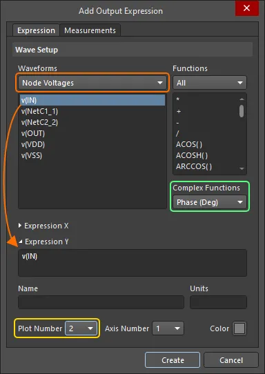
- In the Add Output Expression dialog, select Node Voltages from the drop-down in the Waveform region and click the v(IN) entry in the list below.
- Select Phase (Deg) from the Complex Functions drop-down in the Add Output Expression dialog.
- Select New Plot in the Plot Number drop-down and then click Create in the Add Output Expression dialog.
-
Click the Add control in the Simulation Dashboard panel to add a field for another output expression and the
-
Add an output expression for the phase in degrees of the output signal:
-
Click the Add control in the Simulation Dashboard panel to add a field for another output expression and the button at the right of the added field.
- In the Add Output Expression dialog, select Node Voltages from the drop-down in the Waveform region and click the v(OUT) entry in the list below.
- Select Phase (Deg) from the Complex Functions drop-down in the Add Output Expression dialog.
-
Click the Add control in the Simulation Dashboard panel to add a field for another output expression and the
-
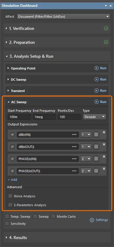
At this point, the AC sweep analysis is configured. Its options should be in the Simulation Dashboard panel as shown below.
-
The simulation configuration file (
project_sim_config.simcfg) will appear in theSettings\Simulation Documentsfolder of the project structure in the Projects panel. Save the document by right-clicking its entry in the Projects panel and selecting the Save As command from the context menu.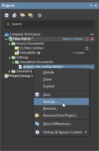
The Save As dialog will open, ready to save the document in the project folder on your hard drive. Click Save to save the document in this default location with the default name.
- Save the project file by right-clicking its entry in the Projects panel and selecting the Save command from the context menu.
Running the Analyses and Exploring the Results
-
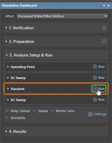
Click the Run button at the right of the Transient region header in the Simulation Dashboard panel to perform the transient analysis.
- When the simulation succeeds, the Messages panel will report about successfully completed simulation. It can be closed.
-
A new simulation result document named
Filter.sdfwill automatically open in the SimData editor as a document tab. It contains a single Transient Analysis chart (indicated by a tab at the bottom of the document), with two plots, each containing a single waveform,v(IN)andv(OUT), respectively.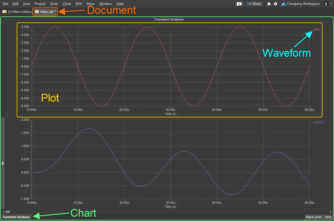
- Switch to the schematic document by clicking its tab at the top of the design space.
-
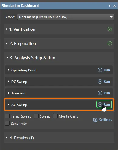
Click the Run button at the right of the AC Sweep region header in the Simulation Dashboard panel to perform the AC sweep analysis.
- Close the Messages panel.
-
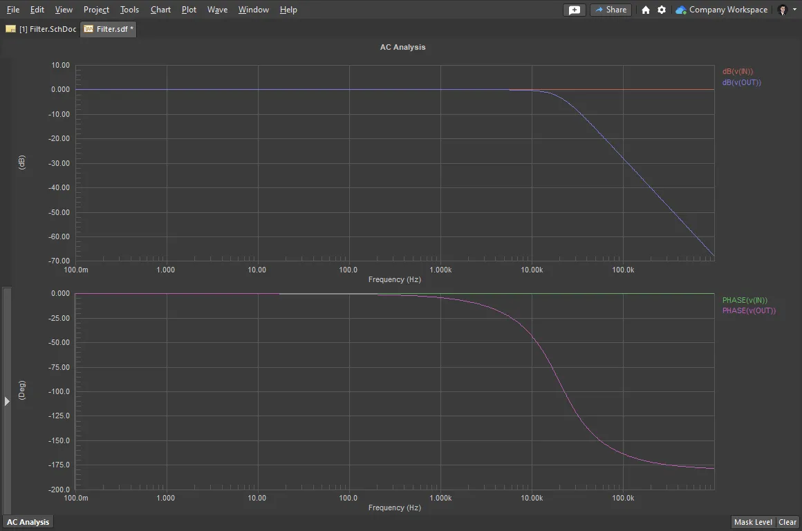
The simulation result document containing a single AC Analysis chart will open. The chart includes two plots, with two waveforms in each.
-
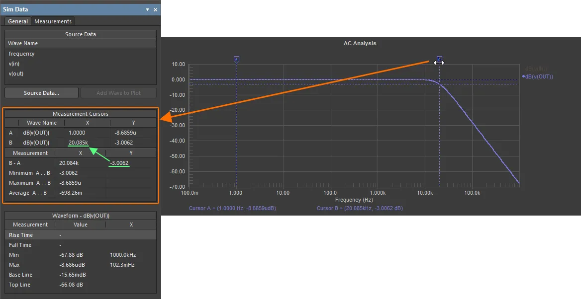
Determine the 3dB point using the measurement cursors:
-
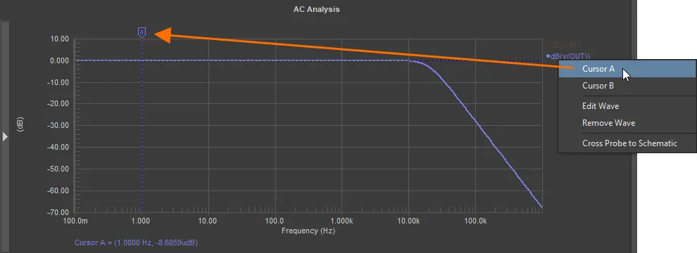
Right-click on the
dB(v(OUT))wave and select Cursor A. -
Position cursor A in the lowpass section by dragging the marker (the location is not critical, as long as it is in the lowpass region).
-
Right-click on the
dB(v(OUT))wave again and select Cursor B. - The Sim Data panel will be used to help locate the cursor (if the panel is not visible, click the Panels button at the bottom-right of the design space and select Sim Data from the menu that appears to display it).
- While watching the B-A Measurement value in the Measurement Cursors region of the Sim Data panel, click and drag Cursor B to give a Y (gain) value of -3.
-
It can be seen that the X result for Wave Name B is appr. 20k, indicating that the 3dB point of the filter circuit is 20kHz.
- To clear the cursors, right-click on each cursor marker and select Cursor Off.
- To clear filtering in the document, click the Clear button at the bottom-right of the design space.
-
Right-click on the
-
The simulation result document (
Filter.sdf) will appear in theGenerated\Simulation Documentsfolder of the project structure in the Projects panel. Save the document by right-clicking its entry in the Projects panel and selecting the Save As command from the context menu.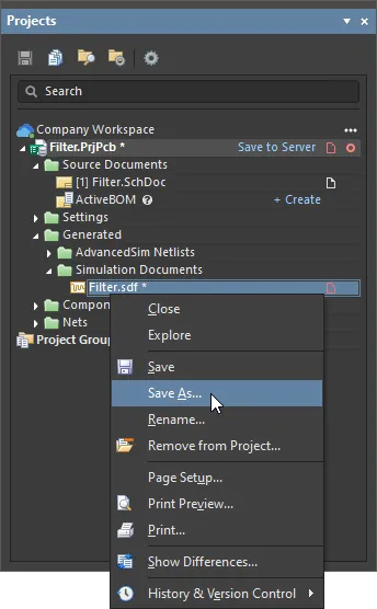
The Save As dialog will open, ready to save the document in the
Simulationsubfolder of the project folder on your hard drive. Click Save to save the document in this default location with the default name. - Switch to the schematic document by clicking its tab at the top of the design space.
-
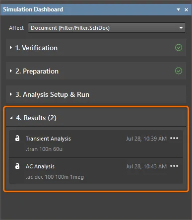
In the Simulation Dashboard panel, expand the Results collapsible region. The region will contain the list of performed simulation runs (Transient Analysis and AC Analysis in this example).
-
To show the results of the transient analysis run previously, click the
 button at the right of the Transient Analysis entry and select Show Results.

The simulation result document will open to show the results of the transient analysis.
- Save modified project documents and the project itself by right-clicking their entries in the Projects panel and selecting the Save command from the context menu.
- If you created the project in your connected Workspace, right-click the project entry in the Projects panel and select the Save to Server command from the context menu and then click OK in the Save to Server dialog that opens.