
Defining Bending Lines - Advanced Mode

To define how a flex board should bend, you place one or more Bending Lines. The Bending Line defines where on the surface of the flex region bending is to take place. The Bending Line also defines the angle and radius of the bend. The width of the strip of board surface that is being bent is displayed in orange, this width is calculated from the bend angle and radius (learn more about the bending line properties). Bending Lines are placed and edited with the PCB editor in Board Planning Mode (View » Board Planning Mode, or press the 1 shortcut).
A Bending Line is placed over the flexible region and configured so the board can fold 180 degrees. This video demonstrates placing a Bending Line in Advanced Rigid-Flex mode.
Placing a Bending Line
To place a Bending Line:
- Select View » Board Planning Mode or press the 1 shortcut to enter Board Planning Mode.
-
Select the Place » Define Bending Line command, or click the
 button on the Active Bar.
- A Bending Line is placed over the required Board Region, it does not attach to it (Bending Lines are associated with one or more Board Regions by the Stack Regions property). Click near the edge of the Board Region to define the Bending Line start location.
- Move the cursor to the required end location and click to place the Bending Line. Note that at least one end of the Bending Line must touch or cross the boundary of the Board Region that it applies to.
- You remain in Bending Line placement mode, ready to place another Bending Line if required. If not, right-click or press Esc to exit Bending Line placement mode.
The properties of a selected Bending Line can be edited in the Properties panel. Because the Bending Line is on top of a region, you might find that when you click on the Bending Line the region underneath it selects instead. Without moving the cursor, click a second time to select the Bending Line instead of the Board Region.

The properties of the selected Bending Line are displayed in the Properties panel.
Moving a Bending Line
To modify the location of an existing Bending Line:
- Select View » Board Planning Mode (or press the 1 shortcut) to enter Board Planning Mode.
- Click and hold on the vertex at either end of the Bending Line, then drag that vertex to the required location and release the mouse button. The cursor will be constrained to the current cursor snap settings, press Ctrl+E to change the settings as you work.
- The bend location will be redefined by the Bending Line's new position.

Select and drag a Bending Line vertex to change the Bending Line's position on the board - the cursor will be constrained by the current cursor snap settings.
Precisely Locating a Bending Line
When the handle of a Bending Line is moved the handle will snap in accordance with the current snap settings. Press Ctrl+E during movement to pop up the snap setting interactive control panel, as shown in the image below. Press Esc after changing settings to apply the settings and close the panel.
As well as snapping to the snap grid and workspace guides, the Bending Line can also be snapped to existing design objects, such as lines on a mechanical layer. The image below shows a Bending Line handle being positioned on the end vertex of a line on a Mechanical layer. Note that the current Hotspot Snap setting applies (shown on the Status bar) during movement, if the mechanical layer is not the active design layer Hotspot Snap must be configured to All Layers for this snap behavior to work. Press the Shift+E shortcut to cycle the Hotspot Snap setting through the available modes, as you work.

The handle of a Bending Line is being snapped to the vertex of a track placed on a mechanical layer.
Removing a Bending Line
To remove a Bending Line:
- Select View » Board Planning Mode (or press the 1 shortcut) to enter Board Planning Mode.
- Click and hold on one of its vertices to select the Bending Line, then press the Delete key.
Configuring the Bending Line Properties
To edit the properties of a Bending Line in the Properties panel:
- Switch to Board Planning Mode (press 1).
- Click anywhere within the orange band of the Bending Line to select it.
-
The Bending Line can be edited in the Properties panel.
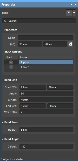
Bending Line Properties
Properties
- Name - the user-definable name of this Bending Line. Naming each Bending Line can help distinguish their function in the design.
- (X/Y) the X and Y location coordinates of the reference vertex of the Bending Line. Edit to change the X or Y position of the Bending Line. Values can be entered in either metric or imperial; include the units when entering a value whose units are not the current default.
Stack Regions
List of all Board Regions that are underneath the selected Bending Line.
- Used - enable the checkbox to apply the Bending Line to the named Board Region.
- Name - the name of the Board Region to which this Bending Line can be applied.
Bend Line
- Start (X/Y) - the X and Y location coordinates of the first Bending Line vertex. Edit to change the X or Y position of that Bending Line vertex.
- Angle - the angle that the Bending Line is oriented in the design space.
- Length - the distance between the Start and End vertices.
- End (X/Y) - the X and Y location coordinates of the second Bending Line vertex. Edit to change the X or Y position of that Bending Line vertex.
- Fold Index - value is used to determine the order that the bends are applied when the rigid-flex board is folded in 3D Layout Mode. The bend with the lowest Fold Index value is applied first, through to the highest Fold Index value.
Bend Zone
- Radius - orthogonal distance from the Board Region surface to a point in space that the bending occurs around.
Bend Angle
- Default - the angle of the applied bend. Enter a negative value to apply the bend in the other direction.