
Designing with Touch Controls
How many of us got into electronics because we were drawn by the myriad of cool switches, knobs, lights and other suitably gadget-centric controls? Fast forward a good few years and that allure is still there, only it is now replaced with the "Snazzy GUI" factor - electronic products that have a sleek, sexy interface. Central to these ever-advancing (and shrinking) product interfaces is touch control. Subtle yet powerful, touch control makes a product more efficient to use, typically lowers the manufacturing cost and, by virtue of replacing mechanical switches and dials – that are at the mercy of inevitable wear and tear – increases the life-span of that product. Pick up your favorite piece of smart technology and you will soon realize that without touch control, it would simply be, well, not so smart - and certainly far less engaging and fun.
Altium Designer provides support for creating planar capacitive sensor patterns on your PCB. The following vendors are supported:
-
Atmel Touch Controls – various self-capacitance and mutual-capacitance sensor patterns (buttons, wheels, sliders) are available, for use with Atmel® QTouch® and QMatrix® sensor controllers.
-
Cypress Touch Controls – various self-capacitance sensor patterns (buttons, sliders) are available, for use with Cypress® CapSense® controllers.
-
Microchip Touch Controls – various self-capacitance sensor patterns (ring, sliders) are available, for use with Microchip® mTouch® controllers.
 . Enabling touch sensor support for a particular vendor installs the relevant library of components needed for the different touch sensor technologies supported for that vendor, including touch wheels, sliders, and buttons. All components are configurable, allowing you to specify the size and orientations of the touch sensor geometries, in accordance with your design requirements.
Sensor Implementation
A touch sensor is implemented in a design by placing and configuring the required sensor type from a dedicated integrated library. Access to the associated configuration dialog (QTouch Component dialog, CapSense Component dialog, or mTouch Component dialog) for a sensor component by right-clicking over the component and choosing Configure from the context menu.
When configured as required, simply update the target PCB – an ECO is used to effect the required changes, resulting in the creation of the sensor pattern for placement on the PCB. Then it's just a case of placing the sensors on the board at the locations they are required to facilitate your product's user interface, then wiring them up to the applicable touch sensor controllers. Each sensor component on the PCB isn't a footprint in the normal sense, but rather the actual copper electrode pattern. An overlaying panel would be placed over a sensor when the board is assembled.
Implementing a touch control is a snap – just place the required sensor type component on the schematic, configure it as applicable to your design needs, then push the changes over to the PCB to obtain the sensor pattern.
The following sections take a closer look at the configurable sensor components available for placement in a design, their configuration options, and the resulting sensor pattern obtained on the PCB side. In each case, the default configurations are presented.
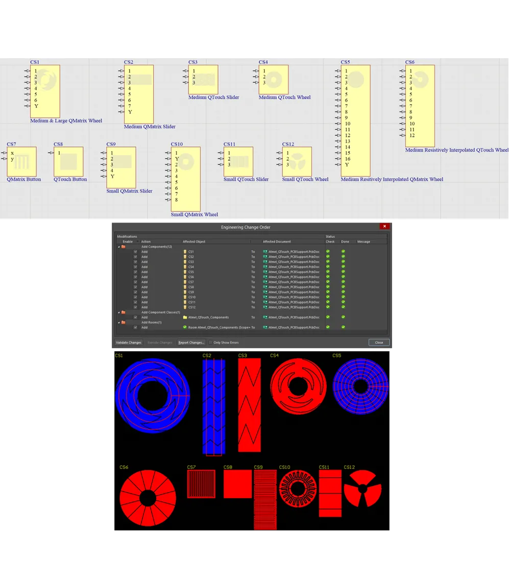
Atmel Touch Controls
Th QTouch Component dialog provides controls to configure a touch sensor component on a schematic sheet when creating planar capacitive sensor patterns on your PCB for use with the range of Atmel® QTouch® and QMatrix® sensor controllers to which the corresponding electrodes from the sensor patterns connect.
Atmel Touch Controls – Supported Self-Capacitance Type Sensors
The following self-capacitance type sensors are supported for use in your PCB designs.
QTouchButton – Button (or Key) Sensor (Single Channel)
Use the QTouchButton component to implement a button (key) sensor. This is a self-capacitance, zero-dimensional sensor, with a single channel for connection directly to an Atmel QTouch sensor controller. The resulting sensor pattern on the PCB is a simple rectangular-shaped electrode.

Default configuration and resulting sensor pattern for the QTouchButton component
The following options are provided:
- height - the height of the sensor pattern (up to 1000mm).
- width - the width of the sensor pattern (up to 1000mm).
SmallQTouchSlider – Small Spatially-interpolated Slider Sensor (3 Channels)
Use the SmallQTouchSlider component to implement a small-size slider sensor. This is a self-capacitance, 1-dimensional, spatially-interpolated sensor, with three channels for connection directly to an Atmel QTouch sensor controller. The resulting sensor pattern on the PCB is comprised of simple rectangular-shaped electrodes. The pattern consists of two full sized electrodes for channels 1 and 2, with channel 3 divided into two half-sized electrodes at either end.

Default configuration and resulting sensor pattern for the SmallQTouchSlider component
The following options are provided:
- height - the height of the sensor pattern (between 5mm and 15mm).
- width - the width of the sensor pattern (between 21mm and 26mm).
- gap thickness - the clearance, or gap, between neighboring sensor channels (between 0.1mm and 0.5mm).
SmallQTouchWheel – Small Spatially-interpolated Wheel Sensor (3 Channels)
Use the SmallQTouchWheel component to implement a small-size wheel sensor. This is a self-capacitance, 1-dimensional, spatially-interpolated sensor, with three channels for connection directly to an Atmel QTouch sensor controller. The resulting sensor pattern on the PCB is comprised of simple wedge-shaped electrodes.

Default configuration and resulting sensor pattern for the SmallQTouchWheel component
The following option is provided:
- diameter - the diameter of the sensor pattern (between 12mm and 20mm).
MediumQTouchSlider – Medium Spatially-interpolated Slider Sensor (3 Channels)
Use the MediumQTouchSlider component to implement a medium-size slider sensor. This is a self-capacitance, 1-dimensional, spatially-interpolated sensor, with three channels for connection directly to an Atmel QTouch sensor controller. The resulting sensor pattern on the PCB is comprised of toothed electrodes. The pattern consists of two full sized electrodes for channels 1 and 2, with channel 3 divided into two half-sized electrodes at either end.

Default configuration and resulting sensor pattern for the MediumQTouchSlider component
The following options are provided:
- height - the height of the sensor pattern (between 4mm and 30mm).
- width - the width of the sensor pattern (between 26mm and 60mm).
- gap thickness - the clearance, or gap, between neighboring sensor channels (between 0.1mm and 0.5mm).
MediumQTouchWheel – Medium Spatially-interpolated Wheel Sensor (3 Channels)
Use the MediumQTouchWheel component to implement a medium-size wheel sensor. This is a self-capacitance, 1-dimensional, spatially-interpolated sensor, with three channels for connection directly to an Atmel QTouch sensor controller. The resulting sensor pattern on the PCB is comprised of toothed electrodes.

Default configuration and resulting sensor pattern for the MediumQTouchWheel component
The following options are provided:
- outer diameter - the outer diameter for the sensor pattern (between 20mm and 60mm).
- inner diameter - the inner diameter for the sensor pattern (6mm or more).
- gap thickness - the clearance or gap between neighboring sensor 'teeth' (between 0.1mm and 0.5mm).
MediumResQTouchWheel – Medium Resistively-interpolated Wheel Sensor (12 Channels, only 3 Connected to the Sensor Controller)
Use the MediumResQTouchWheel component to implement a medium-size wheel sensor. This is a self-capacitance, 1-dimensional, resistively-interpolated sensor, with three channels for connection directly to an Atmel QTouch sensor controller. The resulting sensor pattern on the PCB is comprised of wedge-shaped electrodes.

Default configuration and resulting sensor pattern for the MediumResQTouchWheel component
The following options are provided:
- number of segments between the channels - the number of electrode 'spacer' segments added between the sensor's three channels.
- outer diameter - the outer diameter for the sensor pattern (between 20mm and 60mm).
- inner diameter - the inner diameter for the sensor pattern (between 5mm and 9mm).
- gap thickness - the clearance, or gap, between neighboring electrode segments (between 0.1mm and 0.5mm).
When configuring the sensor, you can choose how many electrode 'spacer segments' are used, equally, between channels. The default configuration uses 3 segments, resulting in 12 wedge-shaped X electrodes in the pattern. Remember that only 3 of these electrodes are connected back to the sensor controller. For this default configuration, the 3 channels connected to the sensor controller are associated with pins 1, 5 and 9 of the component.
To provide the electrically-driven interpolation of the sensors' electric fields, additional resistors must be used in the design, typically connecting a total of 100kOhms between successive channels that are connected to the controller (or 25kOhms between electrode segments). The following image shows an example of resistors wired to the sensor component to provide the required resistance levels, for the default component configuration.

Example of resistors connected to the sensor component to provide the electrical interpolation for the sensor.
Each channel (electrode) of these sensors has a single, direct connection to the sensor controller. Such sensors are non-directional, in terms of their emitted electric fields. Although they can be used with or without an overlying panel, electrostatic discharge (ESD) implications – for the associated controller device – is a major influence for such a panel being used.
All of these sensors are suited for use with Atmel QTouch sensor controllers.
Atmel Touch Controls – Supported Mutual-Capacitance Type Sensors
The following mutual-capacitance type sensors are supported for use in your PCB designs.
QMatrixButton – Button (or Key) sensor (Single Channel)
Use the QMatrixButton component to implement a button (key) sensor. This is a mutual-capacitance, zero-dimensional sensor, with a single channel (one X and one Y electrode) for connection directly to an Atmel QMatrix sensor controller. The resulting sensor pattern on the PCB consists of interlocking fingers of the X and Y electrodes, in an overall rectangular shape. The Pattern for the X electrode completely surrounds that for the Y electrode.

Default configuration and resulting sensor pattern for the QMatrixButton component
The following options are provided:
- height - the height of the sensor pattern (up to 1000mm).
- width - the width of the sensor pattern (up to 1000mm).
- front panel thickness - the thickness of the front panel. This value is used to calculate the thickness of the main 'border' of the enveloping X electrode (typically equal to the panel thickness), as well as the 'fingers' of the X electrode and the spacing between X and Y electrodes (typically half of the panel thickness). The front panel thickness can be between 0.1mm and 10mm.
- width of y side of the sensor - the width of the Y electrode. This should be kept as thin as possible, between 0.1mm and 0.5mm.
SmallQMatrixSlider – 1-layer, Small Spatially-interpolated Slider Sensor (n-channels)
Use the SmallQMatrixSlider component to implement a small-size slider sensor. This is a mutual-capacitance, 1-dimensional, spatially-interpolated sensor, with multiple channels for connection directly to an Atmel QMatrix sensor controller. The resulting sensor pattern on the PCB resembles a 1xn array of buttons, where n is the number of channels defined. X and Y electrodes again are implemented as interlocking fingers. There is a gap between each successive X electrode. The Y electrode is continuous (it is common to all channels), with an additional finger in this gap. Isolated regions of the same X electrode are connected using vias and a track placed on the opposite layer of the board.

Default configuration and resulting sensor pattern for the SmallQMatrixSlider component
The following options are provided:
- number of channels - the number of channels comprising the sensor pattern (between 3 and 8).
- number of segments between channels - the number of additional segments added between the specified channels, allowing for a longer slider to be produced (between 0 and 10).
- front panel thickness - the thickness of the front panel. This value is used to calculate the thickness of the main 'border' of the X electrode (typically equal to the panel thickness), as well as the 'fingers' of the X electrode and the spacing between X and Y electrodes (typically half of the panel thickness). The front panel thickness can be between 0.1mm and 10mm.
- height - the height of the sensor pattern (between 5mm and 50mm).
- width - the width of the sensor pattern (between 24mm and 200mm).
- width of y side of the sensor - the width of the Y electrode. This should be kept as thin as possible, between 0.1mm and 0.5mm.
SmallQMatrixWheel – 1-layer, Small Spatially-interpolated Wheel Sensor (n-channels)
Use the SmallQMatrixWheel component to implement a small-size wheel sensor. This is a mutual-capacitance, 1-dimensional, spatially-interpolated sensor, with multiple channels for connection directly to an Atmel QMatrix sensor controller. The resulting sensor pattern on the PCB resembles a 1xn circular array of buttons, where n is the number of channels defined. X and Y electrodes again are implemented as interlocking fingers, with tapering of the X-electrode fingers. There is a gap between each successive X electrode. The Y electrode is continuous (it is common to all channels), with an additional finger in this gap. Isolated regions of the same X electrode are connected using vias and a track placed on the opposite layer of the board.

Default configuration and resulting sensor pattern for the SmallQMatrixWheel component
The following options are provided:
- number of channels connected to the MCU - the number of channels comprising the sensor pattern, which are connected back to the sensor controller (between 4 and 8).
- number of segments between the channels - the number of electrode 'spacer' segments added between the sensor's specified channels (between 0 and 10).
- panel thickness - the thickness of the front panel. This value is used to calculate the thickness of the main 'border' of the X electrode (typically equal to the panel thickness), as well as the spacing between X and Y electrodes (typically half of the panel thickness). The front panel thickness can be between 0.1mm and 10mm.
- outer diameter - the diameter for the sensor pattern (between 15mm and 21mm).
- width of the y side of the sensor - the width of the Y electrode. This should be kept as thin as possible, between 0.1mm and 0.5mm.
MediumQMatrixSlider – 2-layer, Medium Spatially-interpolated Slider Sensor (n-channels)
Use the MediumQMatrixSlider component to implement a 2-layer medium-size slider sensor. This is a mutual-capacitance, 1-dimensional, spatially-interpolated sensor, with multiple channels for connection directly to an Atmel QMatrix sensor controller. The resulting sensor pattern on the PCB is composed of n slanting X electrodes, where n is the number of channels defined. There is a gap between each successive X electrode. The Y electrode is continuous (it is common to all channels) and consists of a number of horizontal 'fingers'. The Y electrode is located on the Top Layer, with the X electrodes located behind, on the Bottom Layer.
Each X electrode segment is 4mm in height. For a slider that is greater in height, additional segments are essentially stacked, in an alternating zig-zag fashion. An additional Y electrode finger is added for each level of segments in this stack. For the default configuration, where the height of the slider is 12mm, the stack incorporates three segments for each X electrode. The common Y electrode has three fingers.

Default configuration and resulting sensor pattern for the MediumQMatrixSlider component
The following options are provided:
- number of X channels - the number of segments comprising the sensor pattern.
- number of segments between channels - the number of additional segments added between the specified channels, allowing for a longer slider to be produced.
- height - the height of the sensor pattern (between 4mm and 48mm).
- width - the width of the sensor pattern (between 20mm and 150mm).
- gap thickness - the clearance, or gap, between neighboring sensor channels/segments (between 0.1mm and 0.5mm).
- width of y side of the sensor - the width of the Y electrode. This should be kept as thin as possible, between 0.1mm and 0.5mm.
MediumLargeQMatrixWheel – 2-layer, Medium/Large Spatially-interpolated Wheel Sensor (n-channels)
Use the MediumLargeQMatrixWheel component to implement a 2-layer medium-size wheel sensor. This is a mutual-capacitance, 1-dimensional, spatially-interpolated sensor, with multiple channels for connection directly to an Atmel QMatrix sensor controller. The resulting sensor pattern on the PCB is composed of n curved-tooth X electrodes, where n is the number of channels defined. There is a gap between each successive X electrode. The Y electrode is continuous (it is common to all channels) and consists of a number of 'rings'. The Y electrode is located on the Top Layer, with the X electrodes located behind, on the Bottom Layer.
Each X electrode segment is radially 4mm in height. For a wheel that is greater in diameter, additional segments are essentially stacked, radially outward, in an alternating curved-tooth fashion. An additional Y electrode 'ring' is added for each level of segments in this stack. For the default configuration, where the inner diameter is 16mm and outer diameter is 40mm, the stack incorporates three segments for each X electrode. The common Y electrode has three rings accordingly.

Default configuration and resulting sensor pattern for the MediumLargeQMatrixWheel component
The following options are provided:
- number of channels connected to the MCU - the number of channels comprising the sensor pattern, which are connected back to the sensor controller (between 4 and 8).
- number of segments between the channels - the number of electrode 'spacer' segments added between the sensor's specified channels (between 0 and 10).
- outer diameter - the outer diameter for the sensor pattern (between 20mm and 500mm).
- inner diameter - the inner diameter for the sensor pattern (5mm or more, and less than 8mm smaller than the outer diameter).
- gap thickness - the clearance, or gap, between neighboring electrode 'teeth' (between 0.1mm and 0.5mm).
- width of the y side of the sensor - the width of the Y electrode. This should be kept as thin as possible, between 0.1mm and 0.5mm.
MediumResQMatrixWheel – 2-layer, Medium Resistively-interpolated Wheel Sensor (n-channels)
Use the MediumResQMatrixWheel component to implement a 2-layer medium-size wheel sensor. This is a mutual-capacitance, 1-dimensional, resistively-interpolated sensor, with multiple channels for connection directly to an Atmel QMatrix sensor controller. The resulting sensor pattern on the PCB is composed of n curved-tooth X electrodes, where n is the number of channels defined. There is a gap between each successive X electrode. The Y electrode is continuous (it is common to all channels) and consists of a number of 'rings'. The Y electrode is located on the Top Layer, with the X electrodes located behind, on the Bottom Layer.
Each X electrode segment is radially 4mm in height. For a wheel that is greater in diameter, additional segments are essentially stacked, radially outward, in an alternating curved-tooth fashion. An additional Y electrode 'ring' is added for each level of segments in this stack. For the default configuration, where the inner diameter is 7.5mm and outer diameter is 30mm, the stack incorporates three segments for each X electrode. The common Y electrode has three rings accordingly.

Default configuration and resulting sensor pattern for the MediumResQMatrixWheel component
The following options are provided:
- number of channels connected to the MCU - the number of channels comprising the sensor pattern, which are connected back to the sensor controller (between 4 and 8).
- number of segments between the channels - the number of electrode 'spacer' segments added between the sensor's specified channels (between 0 and 10).
- outer diameter - the outer diameter for the sensor pattern (between 10mm and 100mm).
- inner diameter - the inner diameter for the sensor pattern.
- gap thickness - the clearance, or gap, between neighboring electrode segments.
- width of the y side of the sensor - the width of the Y electrode. This should be kept as thin as possible, between 0.1mm and 0.5mm.
When configuring the sensor, you can choose how many electrode 'spacer segments' are used, equally, between channels. The default configuration 4 channels and uses 3 spacer segments, resulting in 16 curved-tooth X electrodes in the pattern. For this default configuration, the 4 channels connected to the sensor controller are associated with pins 1, 5, 9 and 13 of the component.
To provide the electrically-driven interpolation of the sensors' electric fields, additional resistors must be used in the design, typically connecting a total of between 2kOhms and 100kOhms between the n channels that are connected to the controller. The following image shows an example of resistors wired to the sensor component to provide the required resistance levels, for the default component configuration.

Example of resistors connected to the sensor component to provide the electrical interpolation for the sensor.
Each of these sensors has X (transmit) and Y (receive) electrodes, with the mutual capacitance between X and Y measured by the sensor controller. For slider- and wheel-based sensors, multiple channels have unique X-electrode connections to the sensor controller, with a commoned Y-electrode connection. Such sensors should be used with an overlying panel, bonded with no air gaps. It is the panel that provides a suitable conduit for the electric fields between the X and Y electrodes.
All of these sensors are suited for use with Atmel QMatrix sensor controllers.
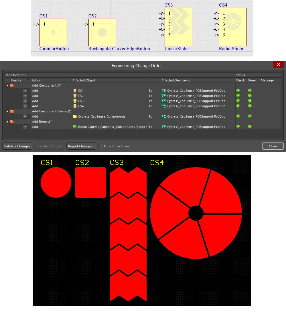
Cypress Touch Controls
The CapSense Component dialog provides controls to configure a touch sensor component on a schematic sheet when creating planar capacitive sensor patterns on your PCB for use with the range of Cypress® CapSense® and PSoC® controllers.
The following self-capacitance sensor types are available for use in your PCB designs.
CircularButton – Circular Button
Use the CircularButton component to implement a button sensor. This is a self-capacitance, zero-dimensional sensor, with a single channel for connection directly to a Cypress PSoC controller. The resulting sensor pattern on the PCB is a simple circular-shaped electrode.

Default configuration and resulting sensor pattern for the CircularButton component
The following options are provided:
- Button Outer Diameter - the outer diameter for the sensor pattern (between 5mm and 15mm).
- Button Inner Diameter - the inner diameter for the sensor pattern (this should be less than the outer diameter with a minimum of 5mm).
RectangularCurvedEdgeButton – Rectangular Curved Edge Button
Use the RectangularCurvedEdgeButton component to implement a button sensor. This is a self-capacitance, zero-dimensional sensor, with a single channel for connection directly to a Cypress PSoC controller. The resulting sensor pattern on the PCB is a simple rounded-rectangular-shaped electrode.

Default configuration and resulting sensor pattern for the RectangularCurvedEdgeButton component
The following options are provided:
- Button Height - the height of the sensor pattern (between 5mm and 15mm).
- Button Width - the width of the sensor pattern (between 5mm and 15mm).
- Button Inner Diameter - the inner diameter for the sensor pattern (this should be less than the width/height with a minimum of 5mm).
LinearSlider – Linear Slider
Use the LinearSlider component to implement an n-segment linear slider sensor. This is a self-capacitance, one-dimensional sensor for connection directly to a Cypress PSoC controller (each segment in the pattern connects to a separate pin of the Controller). The resulting sensor pattern on the PCB is comprised of a 1xn array of double-chevron-shaped electrodes, where n is the number of segments specified. In essence, you are specifying n separate sensors placed physically adjacent to each other. You have global control over the height and width of the constituent sensors. You can also control the gap between neighboring sensors.

Default configuration and resulting sensor pattern for the LinearSlider component
The following options are provided:
- Number of Segments - the number of segments comprising the sensor pattern (minimum of 3).
- Slider Segment Width - the width of each sensor segment (between 2mm and 8mm).
- Slider Segment Height - the height of each sensor segment (between 7mm and 15mm).
- Clearance Between Segments - the clearance or gap between neighboring sensor segments (between 0.5mm and 2mm).
RadialSlider – Radial Slider
Use the RadialSlider component to implement an n-segment radial slider sensor. This is a self-capacitance, one-dimensional sensor for connection directly to a Cypress PSoC controller (each segment in the pattern connects to a separate pin of the Controller). The resulting sensor pattern on the PCB is comprised of n wedge-shaped electrodes, where n is the number of segments specified. In essence, you are specifying n separate sensors placed physically adjacent to each other in radial fashion. You have global control over the inner and outer diameter of the slider, and the clearance between neighboring segments.

Default configuration and resulting sensor pattern for the RadialSlider component
The following options are provided:
- Number of Segments - the number of segments comprising the sensor pattern (minimum of 3).
- Slider Outer Diameter - the outer diameter for the sensor pattern.
- Slider Inner Diameter - the inner diameter for the sensor pattern.
- Clearance Between Segments - the clearance or gap between neighboring sensor segments (between 0.5mm and 2mm).
Each channel (electrode) of these sensors has a single, direct connection to the sensor controller. Such sensors are non-directional, in terms of their emitted electric fields. Although they can be used with or without an overlying panel, electrostatic discharge (ESD) implications – for the associated controller device – is a major influence for such a panel being used.
All of these sensors are suited for use with Cypress CapSense and PSoC controllers.
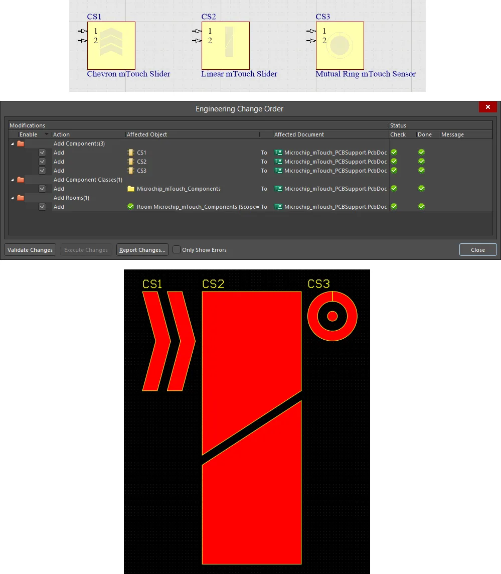
Microchip Touch Controls
The mTouch Component dialog provides controls to configure a touch sensor component on a schematic sheet when creating planar capacitive sensor patterns on your PCB for use with the range of Microchip® mTouch® controllers. Microchip's mTouch Controllers – to which the corresponding electrodes from the sensor patterns connect – are typically PIC devices. The following self-capacitance sensor types are available for use in your PCB designs.
mTouchChevronSlider – Chevron Slider
Use the mTouchChevronSlider component to implement an n-channel chevron slider, for connection directly to a Microchip mTouch sensor controller. The resulting sensor pattern on the PCB is comprised of a 1xn array of chevron-shaped electrodes, where n is the number of devices specified. In essence, you are specifying n separate sensors placed physically adjacent to each other. You have global control over the height and width of the constituent sensors, as well as control over the chevron angle. You can also control the gap between neighboring sensors.
![]()
Default configuration and resulting sensor pattern for the mTouchChevronSlider component
The following options are provided:
- Number of Devices - the number of separate sensors comprising the sensor pattern.
- Slider Width - the width of each sensor segment.
- Height - the height of each sensor segment.
- Angle - the chevron angle (between 0° and 90°).
- Gap Width - the clearance or gap between neighboring sensor segments.
mTouchLinearSlider – Linear Slider
Use the mTouchLinearSlider component to implement a simple 2-channel linear slider, for connection directly to a Microchip mTouch sensor controller. The resulting sensor pattern on the PCB is comprised of two electrodes. In essence, these are two separate sensors placed physically adjacent to each other. Electrode shape is formed by a defined square and triangle. The electrodes are arrange such that their triangular parts almost interlock, separated by a defined gap. This design of slider gives the most linear output as a user's finger passes from one sensor across to the other.

Default configuration and resulting sensor pattern for the mTouchLinearSlider component
The following options are provided:
- Square Height/Width - the height and width of the square-shaped end of each sensor.
- Slider Width - the distance between the square-shaped portion of each sensor.
- Gap Width - the clearance, or gap, between the triangular-shaped parts of each sensor. The gap width must not exceed the total center width.
mTouchMutualRingSensor – Mutual Ring
Use the mTouchMutualRingSensor component to implement a simple 2-channel mutual ring sensor, for connection directly to a Microchip mTouch sensor controller. The resulting sensor pattern on the PCB is comprised of two electrodes, in concentric fashion, with a definable gap between the two. Simply define the radius for the inner pad, and a 'thickness' for the outer pad.

Default configuration and resulting sensor pattern for the mTouchMutualRingSensor component
The following options are provided:
- Outer Pad Width - the width of the outer ring for the sensor pattern.
- Middle Pad Width - the clearance or gap between the inner and outer pads of the sensor pattern.
- Inner Pad Radius - the radius of the inner pad for the sensor pattern.
Each channel (electrode) of these sensors has a single, direct connection to the sensor controller. Such sensors are non-directional, in terms of their emitted electric fields. Although they can be used with or without an overlying panel, electrostatic discharge (ESD) implications – for the associated controller device – is a major influence for such a panel being used.
All of these sensors are suited for use with Microchip mTouch controllers.