
Measuring Distances on a PCB
Designing a printed circuit board is all about accurate sizes and exact measurements. Objects are carefully defined at precise sizes, and accurately placed within the design space. Everything about the printed circuit board requires careful configuration and placement.


The PCB editor supports two styles of measurement, in each of the editing modes:
-
2D editing mode you can: measure the distance between any two points in the editing space, or the distance between any two objects.
-
3D editing mode you can: measure the distance between any two 3D objects, or the distance between two recognized reference points on 3D objects.
Measuring in the PCB Editor
The PCB editor relies on the Unified Cursor-Snap System to locate the cursor in the editing space. Cursor snap occurs when you are taking measurements, playing a fundamental role during the measurement process. For this reason, it is important to understand how to control and configure cursor snapping during editing.
There are two core aspects to the cursor-snap system, what the cursor snaps to, and when it will snap.
-
What - the points in space that the cursor snaps to include: user-defined Grids, work Guides, and snap points on the Objects.
-
When - the cursor snaps to a snap point: when it is within the Snap Distance, and snapping is allowed on that Layer.
A demonstration of various Cursor-Snap behaviors.
Measure Distance between Two Points in 2D
To measure and display the distance between any two points in the current document:
Measuring the distance between two points.
-
Select the Reports » Measure Distance command from the main menus (shortcut:
Ctrl+M). The cursor changes to a cross-hair as you enter measurement mode. -
The Status bar prompts: Select Measure Start Point. Position the cursor on the point where you want to start measuring, then click or press
Enter. -
Move the cursor to the required end point and click, or press
Enteragain. As you move the cursor, a measuring line is displayed as an aid. -
The Measure Distance dialog appears (
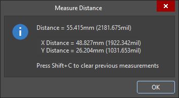 ), reporting: the point-to-point distance, the X (horizontal) distance, and the Y (vertical) distance, in both metric (mm) and imperial (mil) units. To copy the contents of the dialog to the Windows Clipboard, press
 Ctrl+C. -
The measurement is also displayed visually within the design space, showing the measurement's X, Y, and direct distances. The direct (shortest) distance is shown in yellow, with the X and Y distances in light blue. To toggle the results between metric and imperial, press the
Qshortcut key. -
The measurement is also displayed in the Messages panel. Double-click on a result in the panel to return to an earlier measurement, and have its measurement lines displayed again in the design space. The zoom level is configured in the System – Navigation page of the Preferences dialog (
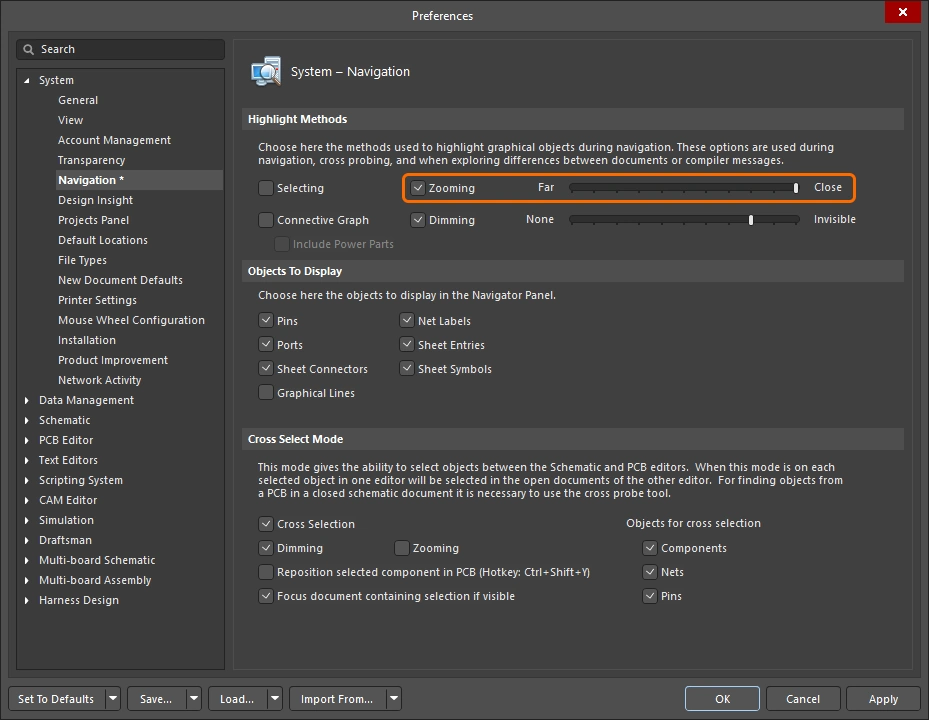 ).
).
-
Continue measuring the distance between other points, or right-click or press
Escto exit measurement mode. -
To clear previous measurements from the design space, press
Shift+C.
Measure Distance between Two Primitive Objects in 2D
To measure and display the distance between the edges of any two primitive objects in the current document:
Measuring the distance between two primitives.
-
Select the Reports » Measure Primitives command from the main menus. The cursor changes to a cross-hair as you enter measurement mode.
-
The Status bar prompts: Choose First Primitive. Position the cursor anywhere over the first primitive, then click or press
Enter. To be able to select a primitive using this command, that primitive type must be enabled in the Selection Filter (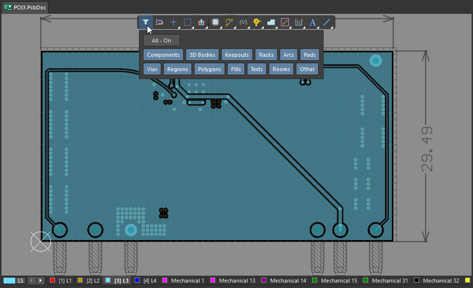 ).
).
-
Move the cursor anywhere over the second primitive, then click or press
Enteragain. -
The Clearance dialog appears (
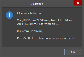 ), reporting the smallest clearance between the two chosen primitives, which may not be at the location where you clicked. The dialog also contains information on the layer and location for each of the primitives. To copy the contents of the Clearance dialog to Windows Clipboard, press
 Ctrl+C. -
The measurement is also displayed visually within the design space, showing the measurement's X, Y, and direct distances. The direct (shortest) distance is shown in yellow, with the X and Y distances in light blue. To toggle the results between metric and imperial, press the
Qshortcut key. -
The measurement is also displayed in the Messages panel. Double-click on a previous measurement result in the Messages panel to cross-probe to that measurement and have its measurement lines displayed again in the design space. The zoom level is configured in the System – Navigation page of the Preferences dialog (
).
-
Continue measuring the distance between other primitives, or right-click or press
Escto exit measurement mode. -
To clear previous measurements from the design space, press
Shift+C.

Measure the Length of Selected Objects
To measure the length of selected tracks and arcs in the current design:
Measuring the length of selected tracks and arcs.
-
Select the tracks and arcs you want to measure.
-
Select the Reports » Measure Selected Objects command from the main menus. Note that selected fills, regions, pads or vias are not included in the measurement.
-
The Information dialog appears (
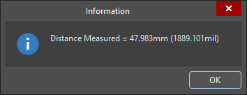 ), detailing the total measured length of the selected tracks and arcs. To copy the contents of the Information dialog to Windows Clipboard, press
 Ctrl+C. -
The measurement is also displayed in the Messages panel.
Measure Distance Between 3D Objects or Faces
To measure distances between 3D objects:
Perform accurate object-to-object measurements in the 3D Layout Mode. The shortest distance between the chosen objects is shown in yellow.
-
Select the Reports » Measure 3D Objects command from the main menus. The cursor changes to a cross-hair as you enter measurement mode.
-
Choose the first 3D object or specific face of that object. As you move the cursor over a potential 3D object, the object color changes to green. To select a specific face of the object, hold the
Ctrlkey as you move the cursor - the face currently under the cursor will be highlighted. When the required object/face is highlighted, click or pressEnterto confirm your selection. -
Before you select the second object, the tool will display measurements for the shortest distance from the underside of this first object (face) to the board surface, and also the shortest distance from this first object (face) to the board edge.
-
Position the cursor to highlight the second 3D object/face, and click or press
Enterto confirm selection. -
The 3D Distance dialog appears (
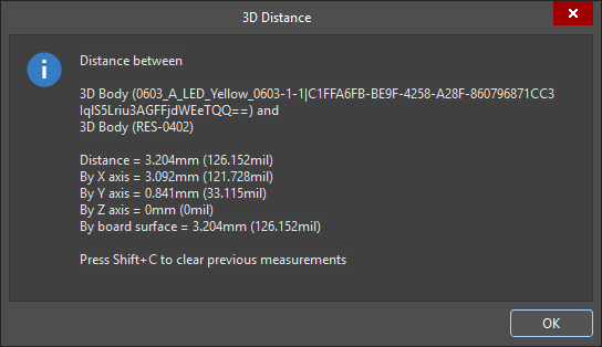 ), reporting: the two 3D objects that were chosen, the shortest point-to-point distance between the objects (at the lowest possible point in the Z-plane), the X-plane (horizontal) distance, and the Y-plane (vertical) distance, in both metric (mm) and imperial (mil) units. To copy the contents of the dialog to the Windows Clipboard, press
 Ctrl+C. -
The measurements are also displayed visually within the design space, showing the X-plane, Y-plane, and direct distances. The direct (shortest) distance is shown in yellow, with the X and Y distances in light blue. To toggle the results between metric and imperial, press the
Qshortcut key. -
The measurement is also displayed in the Messages panel. Double-click on a result in the panel to return to an earlier measurement, and have its measurement lines displayed again in the design space. The zoom level is configured in the System – Navigation page of the Preferences dialog (
).
-
Continue measuring the distance between other objects/faces, or right-click or press
Escto exit measurement mode. -
To clear previous measurements from the design space, press
Shift+C.
Measure Distance between Points on 3D Bodies
To measure distances between two points on the same 3D Body, or between points between two different 3D bodies:
Measure between 2 points on 3D objects.
-
Switch to 3D Layout Mode (shortcut: 3).
-
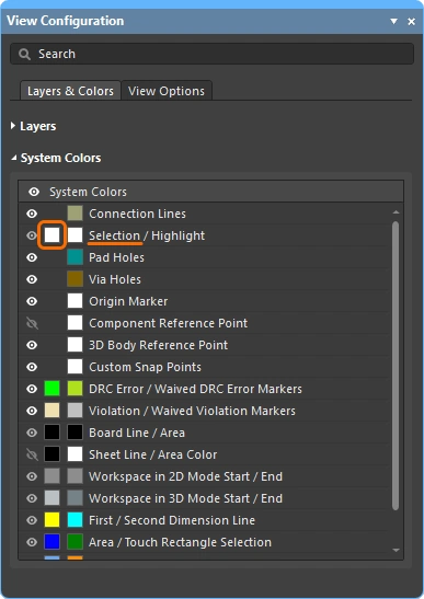
For this type of measurement, it can help to display the reference points in the 3D models, which includes the 3D Reference Points designed into the models, as well as Custom Snap Points that have been added in the PCB library editor (
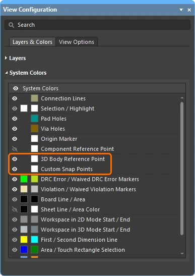 ).
).
-
Choose the Tools » 3D Body Placement » Measure Distances command from the main menus. The cursor changes to a cross-hair as you enter measurement mode.
-
The first click is to nominate the first 3D model to be used, click anywhere on the object. As you move the 3D positional cursor around (blue, six-pointed), it will jump between the available vertices, reference points and snap points in that model (
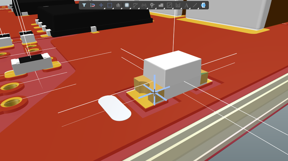 ).
).
-
Position the 3D positional cursor and click to nominate a vertex or snap point as the first measurement point on that 3D model.
-
The next click can either be:
-
Locating a vertex or snap point with the 3D positional cursor on the same 3D model, then clicking to nominate that as the second measurement point.
-
Or you can move the small cross-hair cursor over a different 3D model, click once to nominate that model, then position the 3D positional cursor on a vertex or snap point on that second model and click again to nominate the second measurement point.
-
-
An Information dialog appears (
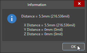 ) showing the direct point-to-point distance, as well as the point-to-point distances along the X-plane, Y-plane, and Z-plane, in both metric and imperial units.
-
Continue to measure further distances, or right-click, or press Esc, to exit.
 ).
).