
Working with the Cursor-Snap System

The PCB Editor is a grid-based design environment - design objects are typically placed on what is referred to as the placement, or snap grid. Multiple snap grids can be defined, and these can be restricted to a specified area if required. Snap grids are prioritized, with the highest priority grid available at the current location, being applied automatically. Snap grids can also be restricted to Components or Non-Components. As well as the snap grid, the software includes a number of additional snap features, designed to help you accurately position and align design objects.
Together, these features are referred to as the Unified Cursor-Snap System. Cursor-snap is the process whereby the physical mouse cursor's pixel position on the screen drives the position of a logical cursor in the coordinate space of a design document such as a PCB. The objective is for the system to be able to place the logical cursor onto sensible and useful coordinates without the user needing to specify these in a high-resolution way. Variable geometry boards - where component pins are often placed on different metric and imperial grids - serve to add greater complexity to this objective.
The system brings together different sub-systems that collectively drive the way the cursor snaps onto a given set of preferred coordinates, including:
| User-Definable Snap Grids | The basic workspace alignment grid, available in both Cartesian and Polar formats. Learn more. |
| Snap Guides | Points and lines that can be freely placed, providing a handy visual and snap cue for object alignment. Learn more. |
| Object Snapping | Enabling placed objects to pull the cursor into position, based on cursor proximity to that object's snap points (hotspots). |
| Control of Object Snapping | Object snapping can be applied on all layers, only the current layer, or disabled. |
| Axis Snapping | A feature to pull the cursor, in either the X or Y direction, so that it axially-aligns with a nearby object's hotspot. |
These features combine to ensure streamlined placement and alignment of objects in the PCB design space.
Understanding the Snap Behavior
The PCB editor design space is a high-precision design environment containing objects that are designed to different scales, sometimes using different units of measurement. The unified cursor-snap system simplifies the process of working in such a complex design space, providing multiple levels of cursor snapping during object placement or movement.
A demonstration of the various Cursor-Snap features.
The PCB editor relies on the Unified Cursor-Snap System to locate the cursor in the editing space whenever an editing action is performed, playing a fundamental role in working in the PCB editor. For this reason, it is important to understand how to control and configure cursor snapping during editing.
There are two core aspects to the cursor-snap system, what the cursor snaps to, and when it will snap.
-
What - the points in space that the cursor snaps to include: user-defined Grids, work Guides, and snap points on the Objects.
-
When - the cursor snaps to a snap point: when it is within the Snap Distance, and snapping is allowed on that Layer.
Setting the Board Origin
The cursor is located within the design space relative to the Current Origin. The snap grid is calculated from this origin, and the position of each placed object is also displayed/defined relative to the current origin. The current origin is user-definable and can be located anywhere in the design space. Use the Edit » Origin » Set command from the main menus to define a location in the design space as the new current origin and set its coordinates to (0,0). After changing the current origin, all objects in the design space will have their locations updated relative to this point.
 ).
).The Snap Points
There are three levels of cursor-snapping available, with each level overriding the lower level(s):
-
Grid(
 ) – the active Grid provides the base-level reference plane for snapping. The logical, or editing cursor, snaps from one grid point to the next as you move the mouse cursor across the screen. Learn more about Working with Grids. Note that multiple grids can be defined, learn more.
-
Snap Guides(
 ) – snap Guides provide a method for the user to define precise, localized reference lines or points. These are snapped to when the Snap Guides option is enabled, with a higher priority than grid snapping. Learn more about Working with Guides.
-
Objects(
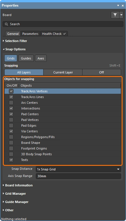 ) – the third, and often the most useful points of reference for snapping, are the objects that have already been placed in the design space. Using the checkboxes in the Objects for snapping list, specific points on each object-type can be enabled as snap points, which are also referred to as object hotspots.
Object Snapping
It is often impossible or impractical to define a grid that all design objects fall on. In that situation, you might need to position a new design object at an off-grid location. The software supports this through a feature called Object Snap, which is essentially a range of attraction around that object's hotspot. Hotspots only exist at meaningful locations, such as the center of a pad or via and the endpoints of track segments.
This is a dual-axis system where the mouse cursor must be within the Snap Distance on both the X and Y axes in order for the object to pull the cursor towards that hotspot. Object hotspot snapping provides an aid to routing electrical objects, especially those that may not fall on the active snap grid. The Snap Distance is configured in the Properties panel when there are no objects selected in the design space.
 Off-grid objects can be snapped to, using the object hotspot snapping feature.
The Objects for snapping feature works in one of three modes. Use the buttons in the Snapping region of the Properties panel (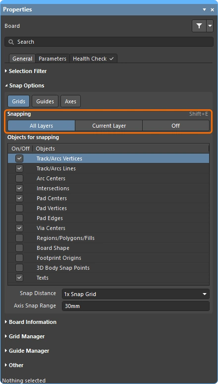 ) to select the required mode. To cycle through the modes as you work use the Shift+E keyboard shortcut, or select the View » Grids » Toggle Object Hotspot Snapping command from the main menus.
When to Object Snap ( |
|
| Current Layer | Object snapping is only enabled for the current layer. When the cursor is within the current Snap Distance, it will snap to object hotspots on the current layer. This mode is reflected in the Status Bar as (Hotspot Snap). |
| All Layers | Object snapping is enabled for all visible layers. That is, the cursor will snap to object hotspots (within the current Snap Distance) on any layer, not just the current layer. This mode is reflected in the Status Bar as (Hotspot Snap (All Layers)). |
| Off | Object snapping is disabled. The Status Bar displays nothing about Hotspot snap in this mode. |
The Snap Strength
The strength of the snap is defined by the Snap Distance. When the mouse cursor moves within this distance from a Snap Point, the editing cursor immediately snaps to that grid / guide / object hotspot. Reducing this value will weaken the snap strength, increasing the value strengthens the snap effect. Keep in mind that a large value for the Snap Distance may prevent you from positioning the cursor at certain grid locations, whenever a nearby object's hotspot is within the Snap Distance.
Select an option from the list, or enter the required value (including the units if it is not the current board units).
 The strength of the snap is defined by the Snap Distance.
Aligning the Editing Cursor with a Placed Object
A common design task is to align a new object with an existing object. This can be achieved by enabling the Axes feature. When this feature is enabled, a dynamic alignment guide line is displayed from the current cursor location to the X or Y aligned object's hotspot whenever the editing cursor is within the Axis Snap Range. This allows an object hotspot that is close to the mouse cursor on one axis but distant on the other axis to drive the cursor position.
 With the axial alignment feature, dynamic alignment guides appear in the design space, from the cursor to the hotspots of existing placed objects.
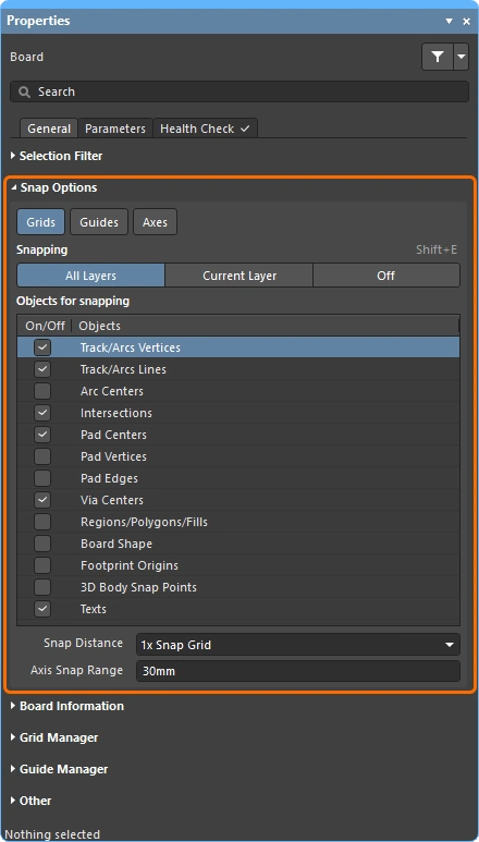
Configuring the Snap Options
The Unified Cursor-Snap System options are configured in the Properties panel (accessed when there are no objects selected in the design space). Use these controls to configure the cursor snapping behavior, including what is snapped to, on which layers, and the range of snapping.
Snap Options ( |
|
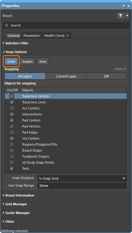
Grids ( ) ) |
When enabled, the cursor will pull or snap to the nearest snap grid location when it is within the current Snap Distance. The active snap grid is displayed on the Status bar and Heads Up display (Shift+H to toggle on/off). When this option is disabled, the cursor will only snap to the enabled Objects for snapping, essentially becoming gridless. Learn more about Working with Grids. |
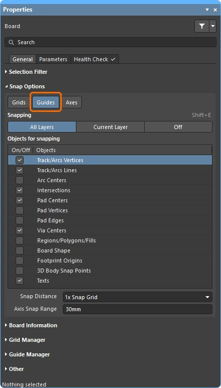
Guides ( ) ) |
When enabled, the cursor will snap to user-defined Work (or Snap) Guides when it is within the current Snap Distance. Note that snapping to a Snap Guide has a higher priority than snapping to the Snap Grid. When this option is disabled, the cursor does not snap to Snap Guides. Learn more about Working with Guides. |
Axes ( ) ) |
When enabled, the cursor will axially-align (in either the X or Y direction) to the enabled Objects for snapping. The Axis Snap Range defines the distance within which X or Y axial-alignment occurs. A dynamic alignment guideline is displayed when alignment is achieved, from the current cursor location to the axially-aligned object snap point. |
Snapping ( ) ) |
Select one of the three buttons to control whether object snapping is: Off, only occurs for the enabled Objects for Snapping on the Current Layer, or occurs for the enabled Objects for Snapping on All Layers. |
| Object for snapping () |
The points (hotspots) on the objects that will be snapped to during an edit action, such as placement, movement, or measurement. Note that the application of these options depends on the current state of the Snapping option above. |
Snap Distance (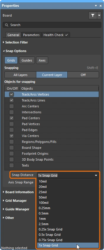 ) ) |
When the cursor is within this distance from an enabled Objects for Snapping (and snapping is enabled for the active layer), the cursor will snap to that point. It will also snap to the current snap grid / user-defined guide when it is within this distance, if the Grids / Guides buttons are enabled. |
Axis Snap Range ( ) ) |
If the Axes button is enabled, a dynamic guideline displays when the cursor is within this distance and is axially-aligned with an enabled Objects for Snapping point. Note that the Snap Distance also applies, pulling the cursor in the X or Y direction to create axial alignment. |
 )
)Interactively Controlling the Snap Behavior
As demonstrated in the video in the Understanding the Snap Behavior section, a key feature of working with the snap options is being able to reconfigure them as you work. This allows you to choose which objects you'd like to enable for snapping, during an edit or placement process.
-
Press Ctrl+E as you work (or click the
 button on the Active Bar) to display a palette of snap options (shown below).
-
Use the three buttons at the top of the palette to enable the required Snap Points.
-
Below the horizontal line there are a set of object buttons that are used to configure the Objects for snapping. Click on an object button once to enable it (the button will turn blue), or click again to disable it (the button will turn gray).
-
Above the object buttons is a tri-state button that reflects what is currently enabled. This button can also be used to cycle through the three possible states: Custom (one to n-1 objects manually enabled), click to switch to; All - On (all objects enabled), click to switch to; All - Off (disabling all objects).
