
Planning Rigid & Flex Regions - Advanced Mode
Placing a Board Region
A Board Region is a polygonal object that is placed using the standard polygonal object placement techniques. The board shape must be precisely defined, so it is important that the regions that make up the board are created exactly as required. The video below demonstrates creating Board Regions by aligning their edges against pre-placed design space guides. The advantage of this technique is that the location of design space guides can be precisely defined by editing their coordinates in the Properties panel.
Pre-defined workspace guides are used as references for the placement of the Board Regions.
Board Regions are placed and modified in Board Planning Mode:
- Select View » Board Planning Mode (or press the 1 shortcut) to enter Board Planning Mode. The default existing Board Region will display as a green rectangle.
-
Select Place » Board Region to place a new region (or click the
 button on the Active Bar).
- Position the cursor and click to anchor the starting vertex for the Board Region. The Board Region is a polygonal object, like a Region or Polygon, and has the same placement (and editing) process.
- Move the cursor ready to place the second vertex. The default behavior is to place 2 edges with each click with a user-defined corner shape between them, press the Spacebar to toggle the corner direction. Refer to the Placement Modes section below for more details on changing corner modes.
- Continue to move the mouse and click to place vertices, creating the edges required to define the overall shape of the Board Region.
- After placing the final vertex, right-click or press Esc to close and complete the definition of the board shape. There is no need to manually close the board shape as the software will automatically complete the shape by connecting the last point placed back to the start point.
- Each Board Region is named to uniquely identify it. Enter a suitable name in the Name field in the Board Region mode of the Properties panel (the Board Region must be selected in the design space to display its properties in the panel).
-
Each Board Region must have a layer stack assigned. When a new Board Region is created it will be assigned the default layer stack, named
Board Layer Stack. Assign the required Layer stack in the Board Region mode of the Properties panel. Layer stacks are defined and named in the Layer Stack Manager. - If the final PCB requires multiple Board Regions, continue to define additional regions.
Additionally, you can press the Tab key to pause the placement and access the Board Region mode of the Properties panel from where its properties can be changed on the fly. Click the design space pause button overlay (![]() ) to resume placement.
) to resume placement.
Placement Modes
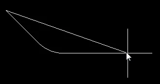
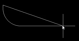
When redefining the board shape there are five available corner modes, four of which also have corner direction sub-modes. During redefinition:
- Press Shift+Spacebar to cycle through the five available corner modes.
- Press Spacebar to toggle between the two corner direction sub-modes.
-
When in either of the arc corner modes, hold the
 key to shrink or the
  key to grow the arc. Hold the Shift key as you press to accelerate arc resizing.
- Press the 1 shortcut key to toggle between placing two edges per click, or one edge per click. In the second mode, the dashed edge is referred to as the look-ahead segment (as shown in the last image in the set below).
- Press the Backspace key to remove the last vertex.


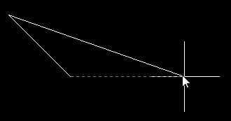
Press Shift+Spacebar to cycle through the five available corner modes, press the 1 shortcut to toggle placement between two edges or one edge.
Board Region Properties

The Board Region mode of the Properties panel.
Actions
These controls are used to add or remove the coverlay from the current Board Region. To enable the Add and Remove Coverlay buttons, the Board Region must have a Layer Stack assigned that has the Is Flex option enabled and has Coverlay layers included in its set of layers.
- Add Coverlay - Add auto-created coverlay polygons to the selected Board Region.
- Remove Coverlay - Remove auto-created and manually defined coverlay polygons from the selected Board Region.
Location
- (X/Y) - the X and Y location coordinates of the first vertex placed when the Board Region was created, relative to the current design space origin. Edit to change the X or Y position of the Board Region. Values can be entered in either metric or imperial; include the units when entering a value whose units are not the current default.
Properties
- Name - user-definable name of this Board Region. Naming each Board Region is helpful when there are multiple regions in the design.
- Layer Stack - specifies which Layer Stack is assigned to this Board Region. The drop-down list will include all Layer Stacks (substacks) defined in the Layer Stack Manager.
- Color - click to open a color palette to set/change the color of the selected Board Region(s). Note that color changes are applied to all board regions that share the Layer stack used by the selected Board Region.
- Priority - the Priority value is used to determine which Board Region is rendered last. Use this when designing a board with a flex region within a board cutout in a rigid region - the flex region must have a higher Priority value than the surrounding rigid region (and the board cutout must trace around the flex-within-cutout region).
- 3D Locked - check this box to fix this Board Region when folding the board in 3D view mode. Only one rigid Board Region can be locked.
Outline Vertices
This region is used to modify the individual vertices of the currently selected Board Region object. You can modify the locations of existing vertices, add new vertices or remove them as required. Arc connections between vertex points can be defined and support is also provided for exporting vertex information to and importing from a CSV-formatted file (via the right-click menu).
-
Vertices Grid - lists all of the vertex points currently defined for the Board Region in terms of:
- Index - the assigned index of the vertex (non-editable).
- X - the X (horizontal) coordinate for the vertex. Click to edit.
- Y - the Y (vertical) coordinate for the vertex. Click to edit.
-
Arc Angle (Neg = CW) - the angle of an arc that is drawn to connect this vertex point to the next. By default, connections are straight-line edges with this field remaining blank. Click to edit then enter an arc angle as required. Entry of a positive value will result in an arc drawn counterclockwise. To draw a clockwise arc, enter a negative value.
-
Add - click to add a new vertex point. The new vertex will be added below the currently focused vertex entry and will initially have the same X,Y coordinates as the focused entry. Click the
 to remove the currently selected vertex.
Create a Board Region from a 3D Body
Board Regions can also be created from 3D Body objects by using the Create Board Region from 3D Body command while in 3D mode. The procedure is as follows:
- Ensure that you are viewing the board in 3D (use the 3 keyboard shortcut to quickly change to this mode, if not).
- Choose the Design » Board Shape » Create Board Region from 3D body command from the main menus.
- Position the cursor over the 3D model that you wish to use in generating the board region for the PCB and click, or press Enter. The model will become transparent.
- Move the cursor over the 3D model to locate a face. Where a flat surface is found under the cursor, it will become opaque with a thin blue border.
- Once the appropriate face has been found, click, or press Enter - the new board region will be created (replacing the previously defined board region in the design space).
- The Board Outline Creation Successful dialog will appear confirming successful creation. This dialog gives you the opportunity to hide the model part and disable it from DRC checking. It also provides options to modify the model height to align the face with the top surface, the bottom surface, or no modification to the position.
Creating a Board Cutout Region
To create an internal cutout in the board, place a Board Cutout Region (Place » Define Board Cutout, or click the ![]() button on the Active Bar). A Board Cutout is also a polygonal object, so has the same placement process as the Board Region itself. The images below show a Board Region with two Board Cutouts, these become holes in the board when it is fabricated.
button on the Active Bar). A Board Cutout is also a polygonal object, so has the same placement process as the Board Region itself. The images below show a Board Region with two Board Cutouts, these become holes in the board when it is fabricated.

 A Board Cutout placed on a Board Region becomes a hole in the finished board.
Slicing the Board Outline into Regions
You can divide an existing Board Region into two regions by slicing it. This is done when the PCB editor is in Board Planning Mode.
The board has been split into three Board Regions using the Slice Region command.
To slice a Board Region:
- Select View » Board Planning Mode (or press the 1 shortcut) to enter Board Planning Mode.
-
Select Design » Slice Board Region (or click the
 button on the Active Bar) to enter Slice Board Region mode.
- When you select the command you are in slice mode, which is similar to track placement mode. Starting outside of the region to be sliced, click to anchor a series of vertex points that define the slice line. When defining the slice, press Shift+Spacebar to cycle through the corner modes; press the Spacebar to toggle between the Start and End corner modes and use the Backspace key to remove the last placed corner. Place the end of the slice line beyond the edge of the Board Region. When you have finished defining the slice, right-click or press Esc to terminate the command.
-
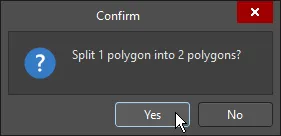
A confirmation dialog opens stating the number of polygons (regions) being split by your action, and the number of polygons (regions) that will be created. Click Yes to confirm their creation.
Creating Board Regions from Selected Objects
Depending on the shape of your board, it can be more efficient to build up the shape by creating multiple Board Regions. As mentioned above, the regions can be interactively placed, or created by tracing an outline defined from track and arc objects. The video below demonstrates defining three Board Regions from selected objects. In the video you will note that the same object is used to define the adjacent edges where the regions touch, ensuring that these regions are exactly positioned.
A common approach is to define the outline of the regions using tracks and arcs, and then create the Board Regions from the selected outlines.
Converting between 2D Drawing Primitives and Board Definition Objects
A common approach to defining the Board Shape, and the Board Regions needed in that shape, is to import a drawing from a mechanical CAD package. For example, you might import mechanical detail in a DWG file, giving you a set of lines (tracks) on a mechanical layer that define: the board shape, the regions within the shape, and for a rigid-flex design, lines that define the location of bend lines in the flexible regions.
The software includes a number of commands to help create board definition objects (Region, Cutout, Bend Line) from 2D drawing primitives, and also partner commands to convert board definition objects back to drawing primitives.
Notes:
- Commands for both directions are available in the Tools » Convert submenu of the relevant View mode (apart from the Create Board Region from Selected Objects command, which is in the Design » Board Shape submenu).
-
To convert 2D drawing primitives to board definition objects, switch the view to 2D Layout Mode.
- The primitive(s) must be selected before running the command.
- The primitives must form a closed shape to create a Region or Cutout. Check the warning box below to learn more about the requirements of this shape.
-
To convert board definition objects to 2D drawing objects, switch the view to Board Planning Mode.
- These commands do not require the object(s) to be pre-selected but will act on the selected object if one is already selected.
- If there are multiple Board Regions present, the Region disappears when it is exploded to primitives. If there is only one Board Region present, the primitives will be created and the chosen Board Region will remain (there must always be one Board Region).
- 2D drawing objects are created on the Board Shape mechanical layer. If a layer of this Layer Type does not exist in the board, a mechanical layer will be added with its Layer Type set to Board Shape. Learn more about Mechanical Layers and Layer Types.
- Although there is no actual command to regroup an exploded object, you can use the Undo command to achieve this.
Modifying the Board Regions
When the PCB is configured to use the standard rigid-flex mode, the location where two adjoining regions meet was defined by a movable blue split line. This approach is not used in the advanced rigid-flex mode, instead, each region is a separate, closed polygonal shape. As a polygonal shape, each region can be adjusted as required using the standard polygonal shape editing techniques. Note that not all polygonal editing commands are available for modifying a Board Region, including the adding and subtracting polygons commands.
Points to remember about editing a polygonal object:
- When you click and drag on a vertex or polygon edge there are 3 reshaping modes available, sliding, breaking, and incurvating - press Shift+Spacebar to cycle through the modes as you are dragging. The current mode is displayed on the Status bar and in the Heads-Up display.
- The cursor snapping behavior is controlled by the current cursor snap settings, which include the current Snap Grid, the available Objects for Snapping, the presence of Workspace Guides, and the Axes Snapping settings - use these features to help you achieve the required shape. Learn more about Understanding the Snap Behavior.
Assigning a Layer Stack and Editing the Board Region Name
Related page: Defining the Layer Stack
When a new board is created, it will have a single region, named Default Layer Stack Region. This region will be assigned the default layer stack named Board Layer Stack.
When you split a board shape into multiple regions, each new region is also assigned the default layer stack. Once the required layer stacks have been defined in the Layer Stack Manager, then each region can have its stack assigned and also can be given a meaningful name.
To assign a layer stack and name a region:
- Select View » Board Planning Mode or press the 1 shortcut to enter Board Planning Mode.
- Click the Multi-Layer tab at the bottom of the workspace to make it the active layer (if the layer tab is not visible, press L to open the View Configuration panel to enable it).
- Double-click on the Board Region to open the Board Region dialog, or single-click on the Board Region and open the Properties panel. If the region does not select and the dialog open, make sure that the Selection Filter is not excluding Regions.
- Assign the Layer Stack by selecting the required stack from the Layer stack drop-down.
- Edit the Name as required.
 is also displayed when the assigned stack is configured as flexible.")
The Board Region's Name and assigned Layer stack are displayed in the geometric center of that region. (Flex) is also displayed when the assigned stack is configured as flexible.