
Single Click Ordering with Altimade
Ultimately, each PCB design should be sent to the manufacturing floor for fabrication and assembly. That can be difficult due to ineffective communication methods between the design and manufacturing teams, incompatible tools and data formats, non-transparent requirements of the manufacturing to the layer stack and design constraints and other considerations.
Altium Designer, in conjunction with the Altimade application, enables you to request an instant quote and place an order to produce your PCB directly from the design environment. Using Altimade, you can access up-to-date prices and lead times and track your orders. All data required for manufacturing is shared via Altium 365, without the need to export and transfer files manually. Altimade modernizes and accelerates the prototype manufacturing process by connecting design, manufacturing, and supply chain data and professionals on Altium 365 to provide an easy, convenient user experience.
Your Interface to Altimade
Your direct interface to Altimade from within Altium Designer is provided courtesy of the Manufacturing panel. This panel is 'command central' for configuring available manufacturing options, performing necessary project checks, and viewing current orders for the PCB.

The Manufacturing panel
Manufacturing Panel Access
The Manufacturing panel can be accessed in the following ways:
-
Click the Panels button on the bottom-right of the design space then select Manufacturing.
- Select the View » Panels » Manufacturing command from the main menus.
Prerequisites
- Before ordering the manufacture and shipment of your PCB design, ensure that you are connected to your Altium 365 Workspace and have opened a project from that Workspace and one of its documents. Use the File » Open Project command to choose a Workspace project from those that have been shared with you. The Manufacturing panel will provide hints for these prerequisites.
-
The PCB project must contain a PCB design document and an ActiveBOM document (
*.BomDoc).
Order and PCB Fabrication Parameters
To define the number of boards to be manufactured and shipped, enter this number in the field below the preview image of the board at the top of the panel. The number must be between 1 and 100.
For defining fabrication parameters, click the Preferences control. Use the drop-downs that appear to select the desirable Solder Mask Color and Silkscreen Color from the lists of available options. Other fabrication parameters displayed below are read-only.

Specify the desirable number of boards to be produced and PCB fabrication parameters.
To calculate the shipment date and minimum cost, click the ![]() button at the top-right of the panel. The project checks will be run, and if any check violations are detected, they will be shown in the panel.
button at the top-right of the panel. The project checks will be run, and if any check violations are detected, they will be shown in the panel.
Project Checks
To order the manufacture of your PCB design through Altimade, it should meet a range of requirements that are monitored by the project checks. Checks and all related violations are located in the Project Checks region of the Manufacturing panel:
-
Manufacturer Constraints – that includes hard-coded checks of the board size (it cannot exceed minimum and maximum limits), layer stack (limits for layer count, total board thickness, etc.), some technological limitations (e.g., for the routing width and drill size), and so on.
When the PCB design meets all manufacturer constraints, the
 icon will be shown next to the Manufacturing Constraint entry. If a violation of any manufacturing constraint check is detected, an entry for it will be shown instead, with the
  icon next to it. The value in brackets in an entry displays the limit value of the manufacturing constraint in violation – e.g.
 (0.127mm)in theMin Trace Width (0.127mm)entry specifies that 0.127mm is the minimum value for routing width (and that the design contains routing of a smaller width). Click the View Details control next to it to cross-probe to the offending object or open the Layer Stack Manager, where applicable. The listed violations must be fixed for proceeding with the PCB manufacturing order.
Manufacturer Constraint check issues will be listed in the Project Checks region of the panel. Use the View Details control to locate and fix the issue where applicable. Hover the cursor over the image to see the panel when there are no Manufacturer Constraint check issues.Below is the list of current Altimade manufacturing constraints.
Constraint Range/value accepted by Altimade Minimum trace width 2.955 mil (0.075mm) Minimum spacing 5 mil (0.127mm) Minimum annular ring 4 mil (0.1016mm) Clearances from edge of board 10 mil (0.254mm) Minimum drill size 3.995 mil (0.101mm) Minimum paste aperture 12 mil (0.3048mm) Minimum silkscreen size 5 mil (0.127mm) Minimum route size 39.37 mil (1.0mm) Board width 0.10 - 14.88 in (2.54 - 377.952mm) Board height 0.10 - 14.88 in (2.54 - 377.952mm) Layer count 2, 4, 6, 8 Soldermask color Blue
Red (default)
Green
Light Green
Matte Green
Yellow
Black
Matte Black
White
Dark Brown
TransparentSilkscreen color Yellow
Red
Green
Blue
Black
White (default)Board thickness 2 Layer Board - 0.2mm
4 Layer Board - 0.4mm
6 Layer Board - 0.6mmInner copper weight 1 oz Outer copper weight 1 oz Surface Finish (the metal plating process that should be used for PCB fabrication) ENIG Logo control No Max drill ratio 10 Max number of unique components 200 Max total placements 600 For recommendations on how to resolve possible violations of these constraints, refer to the collapsible sections below.
Unsupported Copper Layer Count
This violation occurs when the number of the copper layers in the board stackup is not a number acceptable by Altimade.
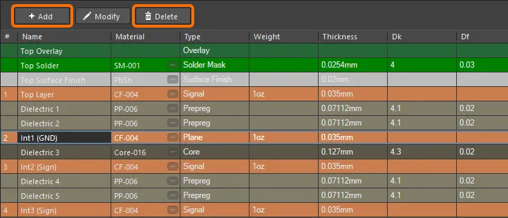
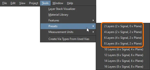
To resolve this violation, change the stackup of your PCB in the Layer Stack Manager. Use the Add and Delete buttons at the top of the Layer Stack Manager's Stackup tab or select one of the layerstack presets (Tools » Presets) to get a layerstack of the copper layer count acceptable by Altimade.
Max Board Thickness Exceeded
This violation occurs when the board thickness is larger than the maximum value acceptable by Altimade.
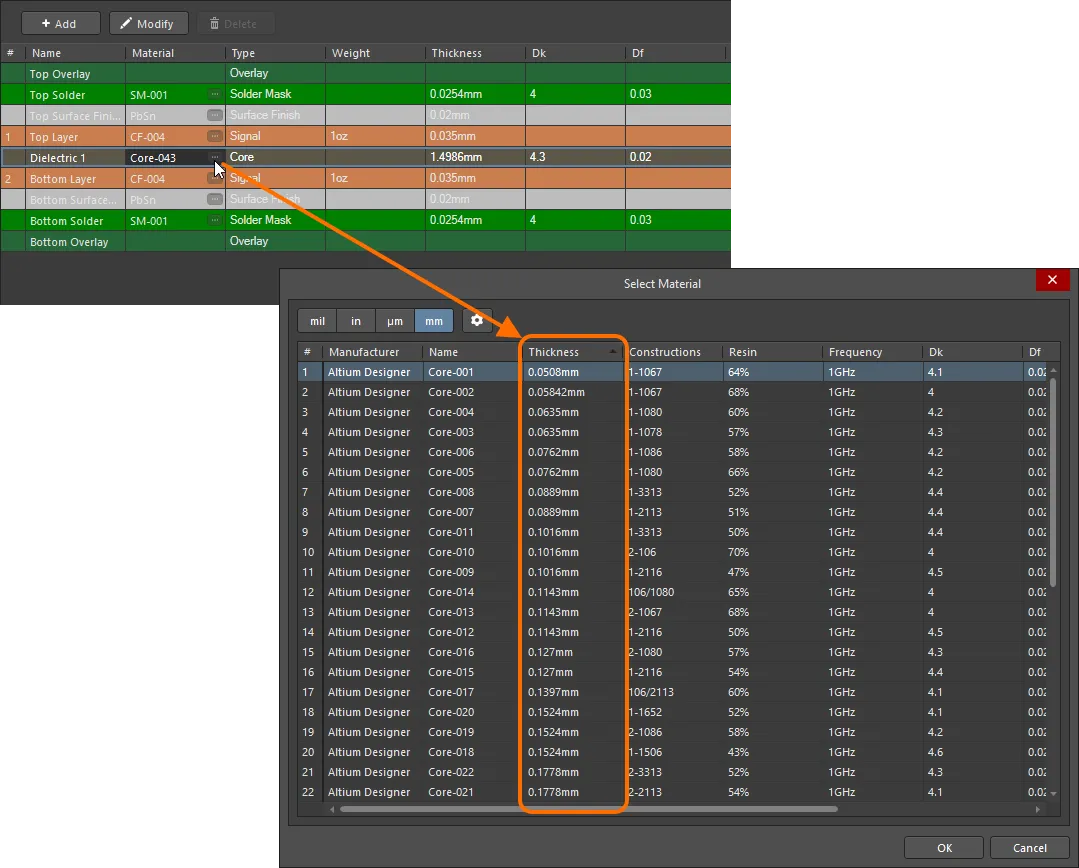
To resolve this violation, change the stackup of your PCB in the Layer Stack Manager. If your PCB is not a controlled impedance board, you can change the material of the PCB core to a material of a smaller thickness.
Copper Weight Is Constrained For All Copper Layers
This violation occurs when there are signal layers in the board stackup which materials have copper weight values other than acceptable by Altimade.
To resolve this violation, change the stackup of your PCB in the Layer Stack Manager. Ensure that all layers of the Signal type use materials of acceptable copper weight.
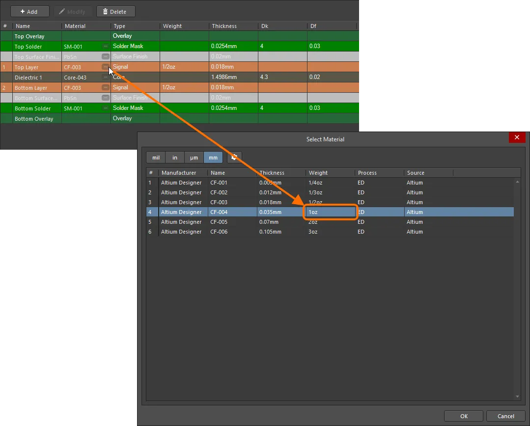
After changing the materials in the Layer Stack Manager, save it, close the PCB document and then reopen it.
ENIG Surface Finish Should Be Present In The Layer Stack
This violation occurs when the board stackup does not contain Surface Finish layers of an ENIG processed material.
To resolve this violation, change the stackup of your PCB in the Layer Stack Manager. Add the Surface Finish layer by right-clicking the top signal layer and selecting Insert layer above » Surface Finish. For the added surface finish layer, select a material of the ENIG process.
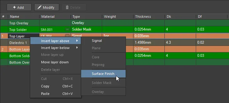
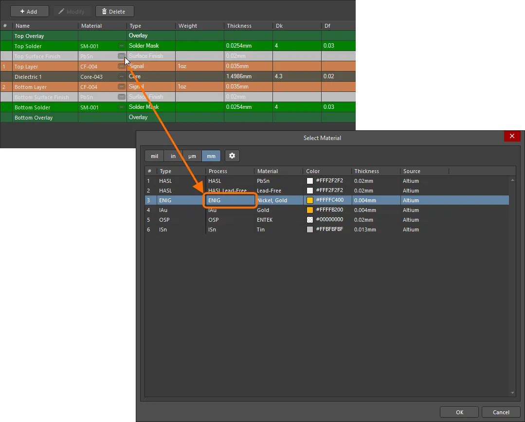
If the layerstack has its Stack Symmetry option disabled, perform the same for the bottom signal layer.
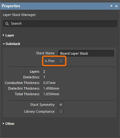
Rigid-Flex Boards Are Not Allowed Yet
This violation occurs when the PCB includes a board region that uses a flex layer stack.
To resolve this violation, ensure that the board regions use only rigid stacks, i.e. stacks with the Is Flex option disabled in the Layer Stack Manager.
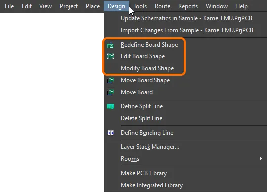
Board Width Is Too Big/Board Height Is Too Big
This violation occurs when the board width/height exceeds the values acceptable by Altimade.
To resolve this violation, change the size of the board. This can be done in the PCB editor's Board Planning Mode (View » Board Planning Mode; shortcut: 1). Use the commands of the Design main menu (Redefine Board Shape, Edit Board Shape, Modify Board Shape) to set the board width/height to a value acceptable by Altimade.
Min Detected Component Pitch Is Too Low
This violation occurs when the design contains a component with a distance between its pads smaller than acceptable by Altimade.
When a component violates the minimum component pitch constraint, its name is displayed for convenience and to speed resolution.
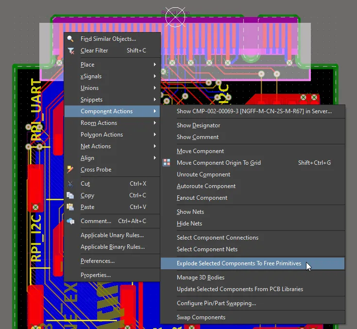
To resolve this violation, the offending component should be excluded from the design. This can be done by exploding the component to free primitives (right-click on the component and select Component Actions » Explode Selected Components to Free Primitives).
The component should also be excluded from BOM (select the DNP option for this component in the Bill of Materials dialog).
Max Unique Component Count Exceeded
This violation occurs when the number of unique components used in the design exceeds the value acceptable by Altimade.
To resolve this violation, reduce the number of unique components used in the design.
Max Total Component Placement Count Exceeded
This violation occurs when the total number of components used in the design exceeds the value acceptable by Altimade.
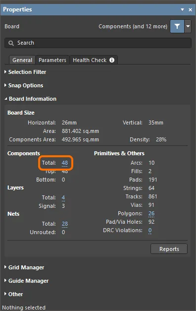
To resolve this violation, reduce the number of components used in the design. The current total number of components is shown in the Board Information region of the Properties panel in its Board mode (active when no object is selected in the design space).
Blind Vias Are Not Allowed/Buried Vias Are Not Allowed
This violation occurs when the design contains via objects other than thru-hole vias.
To resolve this violation, ensure that only thru-hole vias are used in the design. This can be done by converting blind and buried vias to thru-hole vias. To do this, select blind and buried vias using selection techniques of multiple objects (e.g., using the
IsBlindVia Or IsBuriedViaquery in the PCB Filter panel) and then change the Name value toThruin the Properties panel.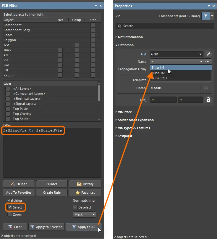
Min Trace Width
This violation occurs when the design contains track and arc objects of width sizes smaller than values acceptable by Altimade on the copper layers.
To resolve this violation, change the width of the offending tracks and arcs. This can be done by selecting these tracks and arcs using selection techniques of multiple objects (e.g., using the
OnCopper And (AsMils(Width) < 3)query in the PCB Filter panel) and then editing the Width value in the Properties panel to a value that can be accepted by Altimade.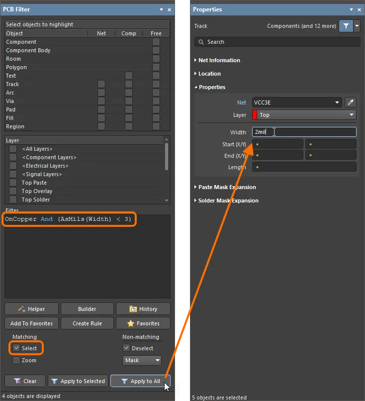
Min Hole Size
This violation occurs when the design contains via and thru-hole pad objects with hole sizes smaller than values acceptable by Altimade.
To resolve this violation, change the hole size of the offending pads and vias. This can be done by selecting these pads and vias using selection techniques of multiple objects (e.g., using the
(IsVia Or IsThruPin) And (AsMils(HoleSize) < 4)query in the PCB Filter panel) and then editing the Hole Size value in the Properties panel to a value that can be accepted by Altimade.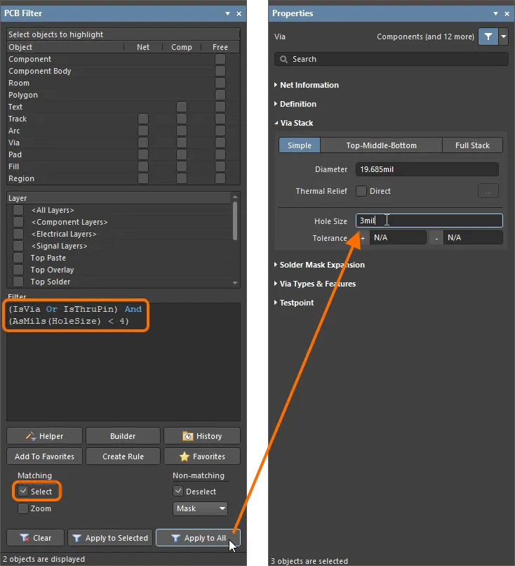
-
Bill of Materials – alongside manufacturer constraints, BOM checks are performed for the PCB to be manufactured through Altimade, including checks such as
End of LifeorObsoletemanufacturer lifecycle state or insufficient stock of a selected part.The following vendors are supported by Altimade:
- Preferred: Digikey, Mouser.
- Standard: Arrow, TTI, Heilind, Sager, Avnet, Newark (UK-based).
- Other sourcing options: DNP (Do Not Populate), Consignment.
When all BOM checks are performed with no issues, the
icon will be shown next to the Bill of Materials entry. If a violation of any manufacturing constraint check is detected, an entry for it will be shown instead, with the icon next to it. Possible BOM violations include Selected part has insufficient stock when the current stock is not enough to assemble the specified amount of boards or when the total value of parts required to assemble the specified amount of boards is less than the minimum order quantity (MOQ) for that part, and Selected part with End of Life or Obsolete lifecycle state when the selected part has insufficient manufacturer lifecycle. Click the View Details control next to it to open the Bill of Materials dialog and review the issues found. To fix an issue from the dialog, you can:
- When the Altimade option is selected as Sourcing – select another part available from the list.
- Select the Consignment option as Sourcing to send your own selected parts to the manufacturer.
- Select the DNP option as Sourcing.
After changing a part, click the Apply Selection button to save the change.

Bill of Materials check issues will be listed in the Project Checks region of the panel. Use the View Details control to open the Bill of Materials dialog and fix the issues. Hover the cursor over the image to see the panel and the dialog when there are no Bill of Materials check issues. -
Design Rule Check – to run a Design Rule Check directly from the Manufacturing panel, use the Run control next to the Design Rule Check entry. A batch-mode DRC will be initiated, and all detected violations will be listed in the Messages panel.

Batch DRC can be run directly from the Manufacturing panel.
Ordering
When the project is checked and there are no issues related to manufacturing constraints and BOM, the shipment date and minimum cost (in USD) will be shown in the panel. Expand the Cost Breakdown region to see the info on cost breakdown in detail.

To see the details of what you are paying for, expand the Cost Breakdown region of the Manufacturing panel.
To proceed with ordering, select the I agree to the Terms of Service checkbox. Click the Terms of Service link to open the Altimade Order Agreement page. Note that this checkbox is shown only for the first checkout. After initial selecting, it will not be shown again.
Click the Review and Checkout button at the bottom of the Project Checks region of the panel to open the Altimade view of the detailed management page for the project (in the Altium 365 Workspace browser interface) in your default web browser for completing the order.

Select the I agree to the Terms of Service checkbox and click the Review and Checkout button to complete the ordering process in the Altium 365 Workspace browser interface.
Back in Altium Designer, the order entries will be displayed in the Orders region of the Manufacturing panel. Click an order entry in the panel to access the order's current information and its details on the Altimade page.

Orders created for a PCB will be listed under the Orders region of the Manufacturing panel.