A Draftsman Drill Table is an automatically generated table object that contains board drill symbols and data. The Drill Table, combined with Draftsman's Drill Drawing View, provides both tabular and graphic information for the board fabrication process. A Symbol row, representing a specified type of drill hole, can include a range of hole information such as its size, plated construction and population count. Holes types are grouped under symbols as specified in the Drill Symbol Configurations dialog.
The table's visual style and data content, including the symbol used, is configurable in (or via) the Properties panel.

A placed Drill Table with hole entries grouped by size.
To place a Drill Table for the current PCB, select Place » Drill Table or use the Drill Table icon ( ) on the table drop-down of the Active Bar. After launching the command, drill hole data is retrieved from the source PCB file, the cursor will change to a cross-hair and the generated Drill Table is attached to the cursor. Move the cursor to the desired position then click to confirm the placement.
The position of a placed Drill Table may be graphically changed by selecting the table in the design space then dragging it to a new location. Note that the table cannot be graphically resized, but will automatically scale to accommodate the font style/size, as specified in the Properties panel.
Select the placed Drill Table to access its property settings in the Properties panel. This provides configuration options for most aspects of the Drill Table, including its visual attributes and data content (through options in the Properties and Column sections).
The Drill Table's Symbol styles, and the grouping of drill hole types under those symbols, is determined by the settings in the Drill Symbol Configurations dialog opened from the Properties panel's  button (in the Properties section). This is the same dialog that is activated from the Properties panel when in Drill Drawing View mode, but in this case, only those columns activated (made visible) for the Drill Table will be shown. Note that the two Drill Symbol Configuration dialogs versions are from the same source and therefore interact.

Options and Controls of the Drill Symbol Configurations Dialog
-
Symbol Graphics - use the drop-down to select the desired hole representation graphic from a range of pre-determined shapes and letters.
-
Sync Symbols with PCB - when enabled, the symbols in the Draftsman Drill Table object are synchronized with those in the PCB.
-
Symbol Size Table - enter the desired size of the symbol table.
Note that the symbol size will change for the currently selected drill symbol(s). To edit the symbol size for multiple drill symbols, hold down the Shift key and click or use the arrow keys. The selected drill symbols will be highlighted. Note also that the size is linked between the Drill Drawing View and Drill Table if the link icon is displayed as

. To set the drill symbol size independently, click the link icon to unlink the two sizes and set the sizes as desired for each.
-
Symbol Size View - enter the desired size of the symbol view. To access and edit this field, the link icon must display as unlinked ( ). Click the link icon to toggle the link status.
-
Symbol Line Style – the thickness and style of the symbol graphics' border/outline. Use the line weight drop-down menu to choose from a range of line thickness presets and the line pattern menu to choose from a range of line styles. The associated color button (
 ) opens the line color selector where the font color can be specified by RGB or HEX value, by freeform selection, or from a range of presets. Note that the slider control sets the color Opacity level, where 0% represents full transparency.
-
Grouping – the chosen criteria will group the selections under one symbol. For example, if only HoleSize is selected, an individual symbol will be assigned to each hole size used in the board. As further grouping options are selected, the symbol assignment will differentiate the additional criteria by creating a finer grouping scheme.
Drill Table Properties

The Drill Table mode of the Properties panel
General Tab
Title
-
Title – the title name string that will be displayed (if enabled) with the Drill Table object. Use
 or
or  to determine whether the string is displayed or hidden (respectively) in the design space. Enter the title name and any desired system/custom parameters to create a meaningful name for the placed view. See the Parameters section in the Properties panel's Document Options mode for a list of the currently available parameters.
-
Location – use the drop-down to choose from a range of relative locations for the title. The Manual option is automatically selected if the title is manually moved (dragged and dropped to a new location).
-
Font – sets the displayed font used for the view's title string.
-
Use Document Font checkbox selected – the title font used is that defined by the document options. See the Document Font entry in the General region of the Properties panel when in Document Options mode.
-
Use Document Font not selected – use the drop-down menus to choose the desired font type and size, and select the lower buttons to enable text attributes. The associated color button () opens the color selector where the font color can be specified by RGB or HEX value, by free-form selection, or from a range of presets. Note that the slider control sets the color Opacity level, where 0% represents full transparency.
Properties
Units
-
Primary Units – select the main dimension unit type that will be shown in the table. Use or to determine whether these units are displayed or hidden (respectively) in the design space.
-
Dual Units – set the secondary dimension unit type that will be shown in the table. Use or to determine whether these units are displayed or hidden (respectively) in the design space.
Precision
Specifies the numerical precision (number of significant digits to the right of the decimal point, with the last digit rounded) for the table's hole size units.
-
Primary Units – use the drop-down menu to choose the numerical rounding for the Primary (main) hole size table entries.
-
Dual Units – use the drop-down menu to choose the numerical rounding for the Dual (secondary) hole size entries (if enabled).
Columns Tab
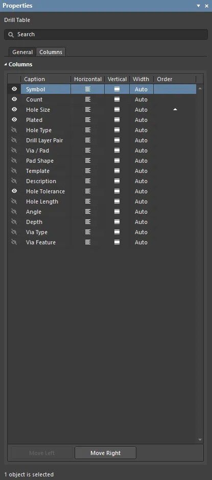
Columns
-
Caption – the column header text. Select to edit the caption.
-
Horizontal/Vertical – the column text alignment. Click to toggle through the alignment options.
-
Width – the width of the column in relation to the text it contains. The Auto option dynamically varies the width to suit the widest column cell text.
-
Order – click the order button (
 ) to cycle between table column data sort order options (off, ascending, and descending). Sorting can be applied to multiple columns on a priority basis, where ordered columns to the left in the table have the higher priority.
-
Move Left/Move Right – click to move the selected column up or down one level in both the sort order priority and the table list position (towards the left or right).
Drill Symbol Tab

This tab is available only in the default object settings in the
Preferences dialog. For a Drill Table placed in a Draftsman document, these properties are available in the
Drill Symbol Configurations dialog. Click the
Drill Symbols button in the
Properties section of the
General tab of the
Properties panel to open this dialog.
 Writer Internal Place
Retired Documentation No Longer Applicable to a Later Version of Altium Designer
Retired Documentation - Manufacturing Output
Writer Internal Place
Retired Documentation No Longer Applicable to a Later Version of Altium Designer
Retired Documentation - Manufacturing Output