Parent page: Streamlining Generation of Manufacturing Data with Output Jobs
A wide range of PCB design fabrication file formats is available for both individual and output job file generation, including:
- Gerber RS-274X and Gerber X2
- ODB++
- IPC-2581
Generating Gerber Fabrication Data
Each file of the Gerber RS274X format (also known as Extended Gerber, or GerberX) corresponds to one layer in the physical board – the component overlay, top signal layer, bottom signal layer, the solder masking layers, etc. This file format includes aperture definitions, XY coordinate locations for draw and flash commands, and other information needed for PCB fabrication.
Gerber X2 is a direct, and much advanced, evolution of the Gerber RS-274X standard and adds a large range of additional data for PCB fabrication and assembly. Compared to the RS-274X standard, the Gerber X2 format includes critical information, such as:
- Layer stack definitions
- Pad and via attributes
- Impedance controlled tracks
A prime advantage of the Gerber X2 format is backward compatibility with the old Gerber RS-274X standard. Being a multi-file standard, a target fab/assembly house that has not moved to the new standard can extract the traditional Gerber file elements as needed. This may be a significant advantage for those unwilling to tackle a major shift in fabrication file formats, or for fabrication houses with inflexible equipment and software.
The overall benefit of adopting the Gerber X2 format for transferring board design data to fabrication and assembly houses is the rich set of manufacturing data included in the file set and the backward compatibility to the previous standard for a low-risk upgrade path. With a full implementation at both ends of the CAD-CAM chain, the risks associated with data misinterpretation, file errors and variable data interpretation can be largely eliminated. In short, both the Gerber X2 and IPC-2581 formats represent a new generation of board design to manufacture data transfer.
With a project PCB file as the active document, the Gerber file set can be generated by selecting File » Fabrication Outputs » Gerber Files or File » Fabrication Outputs » Gerber X2 Files from the main menus. This opens an appropriate Gerber Setup or Gerber X2 Setup dialog in which you can define the plot layers and general configuration applied during the export process. See the collapsible sections below for detailed information on options and controls provided by these dialogs.
This page looks at Gerber file generation using the Gerber Setup and Gerber X2 Setup dialogs available when the UI.Unification.GerberDialog option is enabled in the Advanced Settings dialog. The Advanced Settings dialog is accessed by clicking the Advanced button on the System – General page of the Preferences dialog. If any changes are made in the Advanced Settings dialog, the software must be restarted in order for the changes to take effect.
When the UI.Unification.GerberDialog option is disabled in the Advanced Settings dialog, Gerber file generation is performed using the previous iterations of the Gerber Setup and Gerber X2 Setup dialogs.

Gerber Setup and Gerber X2 Setup dialogs
Output is generated in the location defined in the Output Path field on the Options tab of the Project Options dialog. Generated file names will include the name of the PCB document.
Generated files will be added to the project and appear in the
Projects panel under
Generated\CAMtastic! Documents and
Generated\Text Documents folders.
The generated Gerber output is also opened as a composite CAM document that can be edited and/or saved into the current project and managed via the CAMtastic panel.
To specify if the generated CAM output is automatically opened in Altium NEXUS, enable the
Open outputs after compile option on the
Options tab of the
Project Options dialog (
Project » Project Options).
Options and Controls of the Gerber Setup Dialog

The Gerber Setup dialog. Hover the mouse over the image to alternate between the Layers to plot and Advanced tabs.
Units
Use this region to choose the units used in the generated file:
- Inches – enable this option to use imperial units where all work is done in mils (1 mil = 1/1000 inch).
- Millimeters – enable this option to use metric units where all work is done in millimeters.
Decimal
Use the drop-down in this region to specify the numerical precision of the plot coordinates in the Gerber file.
If you are using one of the higher resolutions, check that the PCB manufacturer supports that format. The 0.1, 0.01 and 0.001 mil formats only need to be chosen if there are holes on a grid finer than 1 mil.
Outputs: FileName.Extension
Use this region to choose the naming option for Gerber files to be generated:
- *.gbr – enable this option to generate layers with unique filenames but with the same single extension (.gbr).
- filename.* (gtl, gbl, gto,...) – enable this option to generate layers with the same filename but with different extensions (.gtl, .gbl, .gto,...).
Others
- Include unconnected mid-layer pads – enable this option to allow unconnected pads in the mid-layer on Gerber plots.
- Generate Reports – enable this option to generate the following files:
.REP, .EXTREP, .apr, .APR_LIB, .DRR, and .LDP.
- Merge regions and pads inside Footprint – enable this option to merge regions and pads within a footprint during the generation of Gerber outputs.
Layers to Plot Tab
This tab allows you to configure which layers to plot in the Gerber output for the current PCB document.
- Layers List – a listing of layers in the current PCB available for output to Gerber. Layers are grouped by their types (Copper Layers, Silkscreen, Solder Mask, Paste Mask, Mechanical Layers, etc.). Each layer is presented in terms of the following:
Click the

button at the far right of the
Layer Name column header to access the
Add Mechanical Layers dialog and select the mechanical layers that are added to all plot layers. Click the
button associated with a layer group to access the
Add Mechanical Layers dialog and select the mechanical layers that are added to all plot layers in the selected layer group.
When Gerber output is generated for a PCB panel (an embedded board array), the dialog includes a column for the panel as well as a column of layers for each board included in the panel. Use this new column to quickly verify that the various board layers are mapped to the correct panel layers.

An example of the Gerber Setup dialog for a PCB document that contains a panel.
- Plot Layers – use the drop-down to access a menu of commands that allow the Plot field for all layers in the Layers to plot region to be enabled or disabled:
- Select All – select to check all boxes in the Plot column (Gerber data will be created for all checked layers).
- Deselect All – select to clear all checked boxes in the Plot column (no Gerber data will be created).
- Select Used – select to check all boxes in the Plot column of the listed layers that are used in the design.
- Edit Group – click to open the Add Mechanical Layers dialog in which you can select the mechanical layers that are added to all plot layers in the selected layer group. You can also click the button associated with a layer group to access the Add Mechanical Layers dialog.
- Mirror Layers – use the drop-down to access a menu of commands that allow the Mirror field for all layers in the Layers to plot region to be enabled or disabled:
- Select All – select to check all boxes in the Mirror column (Gerber data will be created for all checked layers).
- Deselect All – select to clear all checked boxes in the Mirror column (no Gerber data will be created).
- Select Used – select to check all boxes in the Mirror column of the listed layers that are used in the design.
Aperture Matching Tolerances
- Plus – use this box to define the positive tolerance for aperture matching.
- Minus – use this box to define the negative tolerance for aperture matching.
Leading/Trailing Zeroes
- Keep leading and trailing zeroes – if this option is enabled, all leading and trailing zeroes will appear in the generated Gerber file.
- Suppress leading zeroes – if this option is enabled, no leading zeroes will appear in the generated Gerber file.
- Suppress trailing zeroes – if this option is enabled, no trailing zeroes will appear in the generated Gerber file.
Plotter Type
- Unsorted (raster) – select to use raster machine (default).
- Sorted (vector) – select to use vector machine.
Others
- Optimize change location commands – when this option is enabled, X or Y location data is not included if it does not change from one object to the next.
- G54 on aperture change – check this option to rotate the aperture wheel of the plotter after each aperture change.
- Use software arcs – check this option to use software arcs.
- Use polygons for octagonal pads – check this option to use polygons for any octagonal pads.
- Generate DRC Rules export file (.RUL) – check this option to generate a DRC Rules Export file (
.RUL). This file report details the design rules for the source PCB document from which the Gerber data is being generated.
Legacy Tab

The Legacy tab of the Gerber Setup dialog
Film Size
- X(horizontal) – enter a value for the film length.
- Y(vertical) – enter a value for the film width.
- Border size – enter a value for the border size of the film.
Position on Film
Use the following options to choose the position on the film:
- Reference to absolute origin
- Reference to relative origin
- Center on film
Batch Mode
- Separate file per layer – select this option if you want each layer to generate a separate Gerber file.
- Panelize layers – select this option if you want only one Gerber file to be generated in the format of panelization.
Apertures
- Embedded apertures (RS274X) – when this option is enabled, the apertures are embedded in the Gerber files according to the RS274X standard and all information for each layer is contained in a single file. Enabling this ensures that the current apertures list includes all the required apertures. If this option is disabled, the additional controls in this region become available.
- Maximum aperture size – input the maximum size of the apertures for the design.
- Generate relief shapes – check this option to create relief style apertures.
- Flash pad shapes – check this option to flash the pad shapes.
- Flash all fills – check this option to flash all fills.
- Apertures List – lists all the current aperture data.
- New – use the drop-down to access a menu of commands that allow adding a new aperture and save or load the aperture list to/from an aperture file:
- Add Aperture – select to open the Edit Aperture dialog in which you can specify the properties of the new aperture.
- Load – select to open a dialog with which you can select the location of the aperture file to load.
- Save – select to save the current apertures in the apertures list.
- Edit – use the drop-down to access a menu of commands that allow editing of a selected aperture or the apertures list:
- Edit Aperture – select to edit the properties of the selected aperture in the Edit Aperture dialog.
- Rename Aperture – select to edit the properties of the selected aperture in the Edit Aperture dialog.
- Clear All – select to clear all apertures from the apertures list.
- Create List from PCB – select to create the apertures list from the current PCB design.
-
 – select to delete the selected aperture.
Notes about Apertures
Unless your PCB manufacturer does not support embedded apertures, it is highly recommended that you use the Embedded apertures (RS274X) option. Most modern photoplotters are raster plotters that can accept any size aperture. Generally, they also accept Gerber files with embedded apertures.
If your manufacturer does not use embedded apertures, a separate aperture file (*.apt) must be included with the Gerber files. If you use an existing aperture file rather than a generated one, the PCB Editor scans the primitives (tracks, pads, etc.) in the PCB document and matches these with aperture descriptions in the loaded *.apt file. If there is no exact match of aperture to primitive, the PCB Editor will automatically paint the primitive with a suitable smaller aperture. If there is no aperture suitable with which to paint, a *.MAT (match) file will be generated listing the missing apertures and Gerber file generation will be aborted.
The Gerber files should be created with the same format, or precision, as the NC Drill files. For example, if the Gerber files have been configured to use the 0.1 mil format, then the corresponding NC Drill files should use the 2:4 format. If Gerber files have been generated with the coordinate position on the film set to use either the absolute or relative origin, the NC Drill files should be generated using the same origin reference.
Options and Controls of the Gerber X2 Setup Dialog

The Gerber X2 Setup dialog. Hover the mouse over the image to alternate between the Layers to plot and Advanced tabs.
Units
Use this region to choose the units used in the generated file:
- Inches – enable this option to use imperial units where all work is done in mils (1 mil = 1/1000 inch).
- Millimeters – enable this option to use metric units where all work is done in millimeters.
Decimal
Use the drop-down in this region to specify the numerical precision of the plot coordinates in the Gerber file.
The format is selected to suit the placement precision of the objects in the PCB design space and/or fabricator preferences (normally set to the highest resolution: 0.001 mil or 0.00001 mm).
Outputs: FileName.Extension
Use this region to choose the naming option for Gerber files to be generated:
- *.gbr – enable this option to generate layers with unique filenames but with the same single extension (.gbr).
- filename.* (gtl, gbl, gto,...) – enable this option to generate layers with the same filename but with different extensions (.gtl, .gbl, .gto,...).
Others
- Include unconnected mid-layer pads – enable this option to allow unconnected pads in the mid-layer on Gerber plots.
- Generate Reports – enable this option to generate the following files:
.REP, .EXTREP, .apr, .APR_LIB, .DRR, and .LDP.
- Merge regions and pads inside Footprint – enable this option to merge regions and pads within a footprint during generation of Gerber outputs.
Layers to plot Tab
This tab allows you to configure which layers to plot in the Gerber X2 output for the current PCB document.
- Layers List – a listing of layers in the current PCB available for output to Gerber. Layers are grouped by their types (Board Outline, Copper Layers, Silkscreen, Solder Mask, Paste Mask, Mechanical Layers, Drills, etc.). Each layer is presented in terms of the following:
- File Name – the individual Gerber output file name. Naming is based on the project name, layer, and function, and uses an underscore character as a descriptive separator. Click on a layer name to type in a new name if required.
- Layer Name – the layer name that applies to the output file as defined by the board’s layer stack.
- Plot – enable this option to include a Gerber plot for that layer or layer group in the generated output. Disable to exclude the plot from being generated for that layer.
Click the
button at the far right of the
Layer Name column header to access the
Add Mechanical Layers dialog and select the mechanical layers that are added to all plot layers. Click the
button associated with a layer group to access the
Add Mechanical Layers dialog and select the mechanical layers that are added to all plot layers in the selected layer group.
When Gerber X2 output is generated for a PCB panel (an embedded board array), the dialog includes a column for the panel as well as a column of layers for each board included in the panel. Use this new column to quickly verify that the various board layers are mapped to the correct panel layers.

An example of the Gerber X2 Setup dialog for a PCB document that contains a panel.
- Plot Layers – use the drop-down to access a menu of commands that allow the Plot field for all layers in the Layers to Plot region to be enabled or disabled:
- Select All – select to check all boxes in the Plot column (Gerber data will be created for all checked layers).
- Deselect All – select to clear all checked boxes in the Plot column (no Gerber data will be created).
- Select Used – select to check all boxes in the Plot column of the listed layers that are used in the design.
- Edit Group – click to open the Add Mechanical Layers dialog in which you can select the mechanical layers that are added to all plot layers in the selected layer group. You can also click the button associated with a layer group to access the Add Mechanical Layers dialog.
Advanced Tab
Aperture Tolerances
Use the options in this region to set the tolerance range used when matching apertures for each item in the plots.
- Plus – use to define the positive tolerance for aperture matching.
- Minus – use to define the negative tolerance for aperture matching.
If no exact match for an item is available in the current aperture list, the software checks to see if a slightly smaller or larger aperture exists within this tolerance range and uses it instead. If no suitable aperture exists within the tolerance range, the software will attempt to ‘paint’ with a smaller aperture to create the required shape. This requires that a suitable smaller aperture is available and that this aperture can be used for ‘painting’.
Aperture match tolerances are normally used only when targeting a vector photo-plotter, which requires a fixed or supplied aperture file. They will not be required if the apertures have been created from the PCB and ‘flashed’. If match tolerances are not required, they should be left at the default of 0.005 mil.
Plotter Type
Use this region to specify the target photo-plotter type:
- Unsorted (raster) – select to use raster machine (default).
- Sorted (vector) – select to use vector machine.
Gerber files can be created with the data sorted by its position on the ‘film’ or unsorted. Sorting is required only by vector photo-plotters and does not apply to modern raster-style plotters that create an initial image internally. If sorting is enabled, Gerber generation may take an extended time.
Gerber X2 Specific
- File Subject – use this field to select the file type, which is included as a
Part attribute in the Gerber X2 outputs. The drop-down list provides the following choices:
NoneAutodetect – automatically assigns an attribute from the below list based on the type of board file. For example, a PCB document containing a single board design will be assigned the Single part attribute.Single – a single PCB.CustomerPanel – a board array or shipping panel.ProductionPanel – a working panel or fabrication panel.Coupon – a coupon (performance test board associated with a main board design).Other – none of the above. In the file, a string appended to the attribute informally indicates the part.
- File Comment – enter a comment that will be included as an attribute in the generated outputs.
Others
- Optimize change location commands – when this option is enabled, X or Y location data is not included if it does not change from one object to the next.
- Generate DRC Rules export file (.RUL) – enable this option to generate a DRC Rules Export file. The report details the design rules defined for the source PCB document from which the Gerber data is being generated.
Generating ODB++ Fabrication Data
ODB++ is a CAD-to-CAM data exchange format used in the design and manufacture of printed circuit boards. The format was originally developed by Valor Computerized Systems, Ltd., as an open database that could provide a more information-rich data exchange between PCB design software and Valor CAD-CAM software used by PCB fabricators.
With a project PCB file as the active document, the ODB++ file set can be generated by selecting File » Fabrication Outputs » ODB++ Files from the main menus. This opens the ODB++ Setup dialog that provides controls to completely configure ODB++ file output options.

Define export settings in the ODB++ Setup dialog.
Generating IPC-2581 Fabrication Data
Related to the existing ODB++ format, IPC-2581 is an open-source standard developed by the Institute for Printed Circuits IPC-2581 Consortium some years ago (2004), but since refined to the most recent Revision A and B releases (IPC-2581A/B).
The standard has progressively gained wider acceptance as an alternative to the traditional fabrication output data composed of, typically, a collection of Gerber, Drill, BOM, and text files, etc. The previous need for a complex mix of fabrication files is due to the inherent limitations of the traditional RS-274x Gerber format, which lacks definitions for the layer stack, drill information, netlist data (electrical connectivity), and BOM information.
The IPC-2581 standard is officially titled ‘Generic Requirements for Printed Board Assembly Products Manufacturing Description Data and Transfer Methodology’ and offers an XML-based single file format that incorporates a rich range of board fabrication data - from layer stackup details though to full pad/routing/component information, and the Bill Of Materials (BOM).
A single IPC-2581 XML file can include:
- Copper image information for etching PCB layers.
- Board layer stack information (including rigid and flexible sections).
- Netlist for bare board and in-circuit testing.
- Components Bill-of-Materials for purchasing and assembly (pick-and-place).
- Fabrication and Assembly notes and parameters.
The potential advantage of adopting the IPC-2581 format for transferring board design data to fabrication and assembly houses is centered on the highly-defined, detailed single file format that is fully understood at both ends of the chain. With a working system of CAD-CAM data exchange established, the risks associated with data misinterpretation, file errors, and variable Gerber interpretation, are largely eliminated. In short, both the IPC-2581 and Gerber X2 formats represent a new generation of board design to manufacture data transfer.
Functionality is provided courtesy of the IPC2581 extension (a Software Extension).
 The IPC2581 extension
The IPC-2581 functionality can only be accessed provided the IPC2581 extension is installed as part of your Altium NEXUS installation. This extension is installed by default when installing the software, but in case of inadvertent uninstall can be found on the Purchased tab of the Extensions & Updates page (click on the  control at the top right of the design space then choose Extensions and Updates from the menu). If reinstalling, remember to restart Altium NEXUS once the extension has been successfully downloaded and installed.
With a project PCB file loaded as the active document, an IPC-2581 file can be generated by selecting File » Fabrication Outputs » IPC-2581 from the main menu. This opens an initial IPC-2581 Configuration dialog in which you can specify the revision of the IPC-2581 standard to be used (A or B), as well as the measurement units and floating point number precision applied during the export process.

Define export settings in the IPC-2581 Configuration dialog.
The precision setting determines the positional and sizing accuracy of the data within the generated IPC-2581 compliant file as illustrated in the image below.
 and 6 (right).") The same section of an IPC-2581 file with the precision set to 2 (left) and 6 (right).
The same section of an IPC-2581 file with the precision set to 2 (left) and 6 (right).
The XML-based IPC-2581 file will be exported to the location defined in the Output Path field on the Options tab of the Project Options dialog. It will be named using the format <PCBDocumentName>.cvg.
The generated file will be added to the project and appear in the
Projects panel under the
Generated\Text Documents folder.
Fabrication File Output through an Output Job File
To include fabrication file output in a project's Output Job Configuration file, click on [Add New Fabrication Output] under the Fabrication Outputs section then select an output type from the menu and the desired data source from the associated sub-menu.
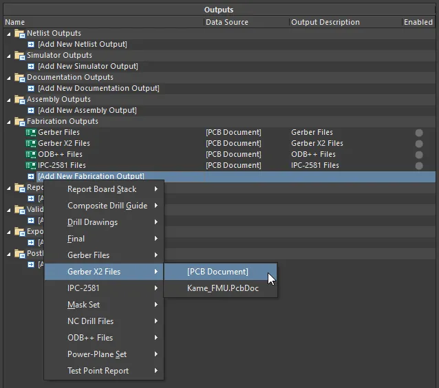
Configure fabrication outputs as part of an Output Job file's Fabrication Outputs. Shown here is an example for Gerber X2 files.
When the OutJob is run – either manually, or as part of the project release process – the fabrication outputs will be generated in accordance with settings defined for the applicable Output Container.

Prepping fabrication outputs as part of a configured OutJob.
The settings defined in related dialogs when generating fabrication outputs directly from the PCB are distinct and separate from those defined for the same output type in an OutputJob Configuration file. In the case of the former, the settings are stored in the project file, whereas for the latter, they are stored in the OutputJob Configuration file.
