
为协同设计准备SOLIDWORKS
Altium CoDesigner 是一个用于在 ECAD 和 MCAD 设计领域之间传输印刷电路板设计的接口。一旦 CoDesigner 插件被添加到您的 MCAD 软件中,CoDesigner 就可以来回传递设计更改。设计更改通过 Altium 工作区传递,该工作区充当 ECAD 和 MCAD 领域之间的桥梁。
► 检查您的 MCAD 软件与 CoDesigner 之间的版本兼容性
在 SOLIDWORKS 中安装和配置 CoDesigner
要在 SOLIDWORKS® 中进行接口操作,您需要安装 Altium CoDesigner for SOLIDWORKS 插件。
 安装并启用插件以在您的MCAD软件中访问CoDesigner。
安装插件:
- 在安装之前关闭SOLIDWORKS。
- 下载并安装SOLIDWORKS插件(AltiumCoDesignerSolidWorks_<VersionNo>.exe)。
- 启动SOLIDWORKS并通过插件对话框启用插件,如上所示。
- 一旦插件被启用,Altium CoDesigner标签页就可以以通常的方式添加到任务面板中。所有的协作活动都通过这个标签页进行。
显示 CoDesigner 任务窗格标签
在 SOLIDWORKS 中,可以在自定义任务窗格标签对话框中启用/禁用任务窗格标签。
 通过SOLIDWORKS任务窗格选项卡访问CoDesigner。
如果 Altium CoDesigner 任务窗格标签(  )没有在SOLIDWORKS中显示:
- 点击任务窗格顶部的设置齿轮,如上所示。将打开自定义任务窗格标签对话框。
- 在对话框中,启用Altium CoDesigner标签。
从SOLIDWORKS连接到您的工作区
SOLIDWORKS 通过工作区与 Altium Designer 合作,您必须在首次使用时登录。
当您未登录时,Altium CoDesigner 标签页将包含登录字段,如下所示。有两种登录模式,一种是登录到 Altium 365 工作区,另一种是登录到位于本地企业服务器上的工作区。
连接到 Altium 365 工作区
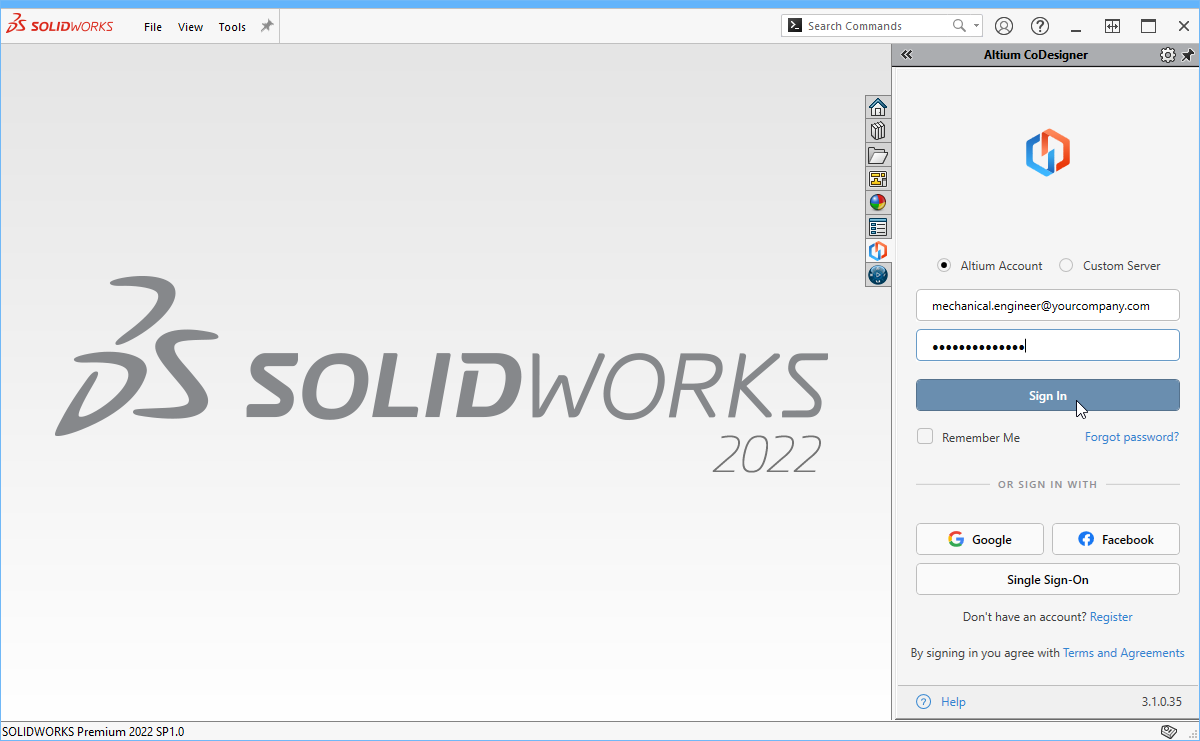登录到 Altium 365 工作区。
- 在Altium CoDesigner任务窗格选项卡中选择Altium 账户选项。
- 输入您用于登录 Altium Live 的电子邮件地址作为您的电子邮件,以及您的 Altium Live 密码。
- 启用记住我选项以保留详细信息(包括密码),并在每次启动 SOLIDWORKS 时自动连接到您的 Altium 365 工作区。
- 点击登录按钮进行连接。
支持多个工作区 - 打开CoDesigner菜单并选择所需的工作区。  连接到Altium企业服务器工作区
 登录到本地企业服务器工作区。
- 在Altium CoDesigner任务面板选项卡中选择使用自定义服务器选项。
- 首次登录时,您必须指定服务器地址(URL)以连接到您的本地企业服务器工作区。地址将由您的系统管理员提供。
- 输入您的用户名和密码,这些也将由系统管理员提供。
- 启用记住我选项以保留详细信息(包括密码),并在每次启动SOLIDWORKS时自动连接到您的工作区。
一旦您登录,就可以开始通过Altium CoDesigner进行协作了。
 CoDesigner 已安装并准备就绪。
配置 SOLIDWORKS 协作设置
登录后,可以通过 CoDesigner 菜单中的设置菜单项打开的Altium CoDesigner 设置对话框来配置 CoDesigner 设置(显示图片)。

 在设置对话框中配置 CoDesigner 选项。
- 存储来自ECAD的模型的通用文件夹 - CoDesigner创建的所有组件模型都存储在此位置,无论它们属于哪个项目(请注意,板件部分和板件装配体是由CoDesigner在初始拉入Solidworks时指定的项目文件夹中创建的)。如果未指定位置,则所有组件模型将在项目文件夹中创建,并且无法在其他项目中重用。
-
为铜建立3D几何体- 顶层和底层铜层始终作为贴花表示在板件的表面上。启用此选项时,CoDesigner还将创建挤出特征来表示所有铜层以及通孔垫。请注意,启用此选项可能会创建大量数据,从而显著影响性能。
 请参阅右侧面板中的注意了解功能可用性信息。
-
构建通孔- 启用此选项还包括通孔桶。请注意,启用此选项可能会创建大量数据,从而显著影响性能。请参阅右侧面板中的注意了解功能可用性信息。
-
平面文件夹结构 - 启用此选项时,子部件和装配文件存储在与主装配文件相同的文件夹中。禁用该选项时,所有子部件和装配文件都存储在子文件夹
\<McadAssyName>-EDM中。如果您使用SOLIDWORKS与Windchill作为产品数据管理系统,建议使用平面文件夹结构。 - 将大于<Size><Units>的板材草图孔转移到ECAD作为切口 - 板材轮廓草图中包含的任何孔,如果可以在ECAD中解释为垫片(包括圆形、方形或槽形孔),且孔大小(或槽宽)等于或小于此值,将被转换为ECAD中的自由垫片。大于此值的孔将被转换为板材切口。不对应于方形或槽形的非圆形孔始终转换为板材切口,无论大小如何。
-
忽略高度小于
<Value><Units>的组件 - 可以从同步过程中排除较小的组件。配置此选项以在执行拉取操作时排除高度小于<Value><Units>的组件。请注意,组件高度在ECAD中定义为组件(印迹)的属性,它不是放置在印迹上的3D模型的高度。了解更多关于配置CoDesigner以忽略较小组件的信息。 - 参与产品改进计划 - 启用此选项以自动共享有关您使用MCAD CoDesigner的技术信息给Altium。了解更多关于产品改进计划。
在SOLIDWORKS中工作
本节详细介绍了在使用Altium MCAD CoDesigner时,SOLIDWORKS特定的重要设置。
如果您计划使用 MCAD CoDesigner 的线束设计功能,您需要安装 SOLIDWORKS Routing Electrical 才能同步线束(包含在 SOLIDWORKS Premium 包中)。请注意,SOLIDWORKS Routing Electrical 还需要安装 Microsoft Excel 才能读取线束连接信息。了解更多关于SOLIDWORKS 和 MCAD CoDesigner 的线束同步。 SOLIDWORKS 默认模板 为了避免每次创建新组件时都被提示选择组件模板,建议配置并使用默认模板,如下所示。这些可以是提供的SOLIDWORKS模板,或者是您自己公司的模板。定义零件、装配体和图纸的模板位置,并选择始终使用这些默认文档模板,如下所示。  配置您偏好的SOLIDWORKS模板。
SOLIDWORKS中PCB铜、掩膜和丝印的显示
CoDesigner将顶层铜、顶层焊膏防护层和顶层丝印合并成一个单一的顶侧贴花,并且对板子的同样底侧层重复此过程。当电路板被拉入MCAD时,这些顶侧和底侧的贴花就会被应用。
 顶部贴花是顶部铜层、顶部阻焊层和顶部丝印层的组合。
关于贴花的说明:
- 如果贴花显示不正确,可能是SOLIDWORKS中的渲染问题。有关认证视频卡和最新视频驱动程序更新的更多信息,请参考https://www.solidworks.com/support/system-requirements。请注意,该页面包括一个指向认证卡和驱动程序的链接,您可能可以从那里下载视频卡的更新补丁。
- 如果上一步没有解决贴花的显示问题,尝试在SOLIDWORKS 系统选项对话框的性能页面切换增强图形性能选项(显示图片)。对于某些视频卡,禁用此选项会有帮助,对于其他视频卡,启用它会有帮助。
- 如果在CoDesigner设置中启用了为铜和阻焊膜构建3D几何形状模式,每个铜和阻焊膜层都作为单独的层传输,它们不会合并成一个贴花。在这种模式下,丝网细节作为贴花应用于阻焊层。了解更多关于CoDesigner如何处理铜、掩膜和覆盖层

SOLIDWORKS中的贴花存储
为了更好地支持使用SOLIDWORKS与PDM系统的设计师,CoDesigner将贴花(代表铜层、丝印层和阻焊层的图像文件)直接保存到板件文件中。这简化了在MCAD端使用PDM系统时,与PCB相关文件的管理。
 贴花存储在SOLIDWORKS prt文件中,简化了使用SOLIDWORKS和PDM系统工作的过程。
使用多个版本的SOLIDWORKS
如果您的公司使用多个版本的SOLIDWORKS,那么您会意识到SOLIDWORKS不支持在旧版本的SOLIDWORKS中打开更新的文件。如果您配置了CoDesigner以使用共享文件夹来存储模型,那么这可能会成为一个问题,因为使用更新版本SOLIDWORKS的工程师可能会覆盖共享模型,使得使用旧版本SOLIDWORKS的工程师无法使用这些模型。
CoDesigner 将公共模型文件夹路径存储在配置(config)文件中:
-
文件:
SolidworksAddin.config -
位置:
%localappdata%\Altium\Altium CoDesigner\Config\
该文件在启动 SOLIDWORKS 时加载,并在退出 SOLIDWORKS 时保存。如果您需要使用多个版本的 SOLIDWORKS,并希望配置 Altium MCAD CoDesigner 以支持每个版本的不同公共模型文件夹位置,您可以为希望运行的每个 SOLIDWORKS 版本创建一个唯一的配置文件。
为此:
- 为您将要使用的每个 SOLIDWORKS 版本创建配置文件的副本。
-
在每个配置文件的文件名中包含 SOLIDWORKS 版本;例如
SolidworksAddin2023.config。 -
可以通过以下方式定义每个 SOLIDWORKS 版本中所需的唯一模型路径:编辑配置文件中的
SolidWorksPartsLibraryFolderPath键的Value(如下所示),或者运行 SOLIDWORKS 并在 Altium CoDesigner 设置 对话框中编辑路径。
 配置配置文件,以便使用唯一的CoDesigner模型路径启动每个版本的SOLIDWORKS。
为CoDesign配置SOLIDWORKS PDM
SOLIDWORKS PDM客户端
当您使用SOLIDWORKS PDM时,一个有用的补充是SOLIDWORKS PDM客户端。客户端提供对PDM保管库(服务器)的访问权限,允许您浏览和探索PDM保管库的内容。 - PDM客户端通过SOLIDWORKS安装管理器安装([显示图片](/documentation/sites/default/files/wiki_attachments/303776/SW_Installer2.png))。 - 您还需要一个保管库视图,它允许在Windows文件资源管理器中显示保管库内容。一旦PDM客户端安装完毕,保管库查看器将可供安装([显示图片](/documentation/sites/default/files/wiki_attachments/303776/SW_ViewSetup.png))。 #### PDM设置
- 在 SOLIDWORKS PDM 设置中(通过 SOLIDWORKS 中的工具菜单访问)禁用如果以只读模式打开文件则提示签出文件选项,如下所示。这样做意味着现有组件将不需要签出,因此不会给其他机械工程师带来不便。然而,当需要更改组件属性时,应该签出相应的组件。

SOLIDWORKS 产品数据管理(PDM)是一种本地数据管理解决方案,支持团队管理和在产品开发期间的协作。
建议保持在 PDM 控制之下
- CoDesigner存储模型的公共文件夹。在Altium CoDesigner 设置对话框中配置指定的用于存储模型的公共文件夹选项,将该文件夹置于SOLIDWORKS PDM控制之下,并在与ECAD协作前与本地存储同步。
-
对于MCAD CoDesigner 3.7或更早版本,包括
\Orig和\Expt子文件夹。 - 对于MCAD CoDesigner 3.8及更高版本,如果使用Windchill作为产品数据管理系统,建议在Altium CoDesigner 设置对话框中启用扁平文件夹结构选项。
- 与PCB项目相关的装配体和零件。
无需置于PDM控制之下
- PNG文件用于生成贴花(代表铜、丝印和防焊膜的图片)。这些图像文件存储在与板件相同的文件夹中。
下一步去哪里?
既然CoDesigner已经安装在您的MCAD软件中并且已经连接到您的工作区,下一步就是配置相关的工作区设置。
► 了解更多关于配置您的工作区设置
 AI-localized