 Altium Designer 文档
...
((Design Objects Reference))_AD
Schematic Design Objects in Altium Designer
Altium Designer 文档
...
((Design Objects Reference))_AD
Schematic Design Objects in Altium Designer
在Altium Designer中在原理图页面上使用总线对象
Parent page: Schematic Objects
 A Bus is a polyline object that is used, in conjunction with other connected objects, to define the connection of multiple nets.
Summary
A Bus is a polyline object that represents a multi-wire connection and is an electrical design primitive.
Availability
Buses are available for placement in the Schematic Editor only by:
- Choosing Place » Bus from the Schematic Editor main menus.
- Clicking the Bus button (
 ) in the net wiring objects drop-down on the Active Bar located at the top of the workspace. Click and hold an Active Bar button to access other related commands. Once a command has been used, it will become the topmost item on that section of the Active Bar.
 - Clicking the button on the Wiring toolbar (View » Toolbars » Wiring to activate).
- Right-clicking and choosing Place » Bus from the context menu.
Placement
After launching the command, the cursor will change to a cross-hair indicating Bus placement mode. Placement is made by performing the following sequence of actions:
- Click or press Enter to anchor the starting point for the Bus.
- Position the cursor then click or press Enter to anchor a series of vertex points that define the shape of the Bus.
- After placing the final vertex point, right-click or press Esc to complete placement of the Bus.
- Continue placing further Bus objects or right-click or press Esc to exit placement mode.
- Use the Backspace or Delete keys to remove the last Bus segment placed.
Placement Modes
When placing a Bus there are three 'manual' placement modes, two of which have corner direction options. The modes specify how corners are created when placing buses and the angles at which buses can be placed.
During placement:
- Press the Tab key to pause the placement and access the Bus mode of the Properties panel from where its line properties can be changed on-the-fly. Click the workspace pause button overlay (
 ) to resume placement.
 - Press Shift+Spacebar to cycle through the three manual modes:P 90°, 45° and Any Angle.
- While in the 90°or 45° mode (known as true orthogonal modes), press Spacebar to cycle between the corner direction options. In these modes, the line segment attached to the cursor is a look ahead segment – the actual segment being placed precedes this look-ahead segment.
- During placement, the current placement mode is displayed in the Status bar (at the very bottom of the workspace). You can change modes at any time during Bus placement.
 45 degree mode
 90 degree mode
 Any angle modePress Shift+Spacebar to cycle through the different placement modes.
Automatic Path Mode
The fourth available Bus placement mode is an Auto Wire mode, which can be used to route quickly from the previous segment end to the point where the cursor is clicked using the Point to Point Router. When enabled during the Shift+Spacebar selection cycle, the mode is indicated by a thick dotted line from the segment vertex to the cursor.
, the Bus path will automatically avoid obstacles.") Placing a Bus segment in Auto Wire mode, as indicated by the dotted path line. When placed (right), the Bus path will automatically avoid obstacles.
Placing a Bus segment in Auto Wire mode, as indicated by the dotted path line. When placed (right), the Bus path will automatically avoid obstacles.
The path of the route will be the most efficient possible, while avoiding existing placed objects on the sheet. Press Tab while in this mode to configure applicable options in the Point to Point Router Options dialog.
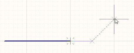
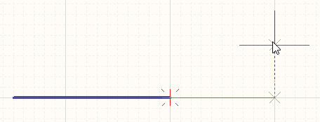
Electrical Snap
Along with its snap to grid feature, the schematic editor also supports snapping to available electrical connections. When an object being placed, such as a Bus, falls within a definable snap distance of a valid electrical connection, the cursor will jump to that electrical 'Hotspot' (shown as a red cross).
 The electrical snap point is indicated by a red cross.
Electrical Object Hotspot snapping is configurable in the General section of the Properties panel when in schematic Document Options mode.
Graphical Editing
The graphical editing method allows a placed Bus object to be selected directly in the workspace and its size and/or shape graphically changed.
When a Bus object is selected, the following editing handles are available:
 Selected Bus, ready for graphical editing.
- Click and drag a non-handle point to reposition the entire Bus. When a Bus is not selected, click, hold and drag to reposition it.
- Click and drag A to reposition the end points of the Bus.
- Click and drag B to move a Bus vertex. The other vertices will remain anchored.
- Click and hold on a vertex then press Delete on the keyboard to remove that vertex.
With the Bus selected, click on a segment to individually select that segment. This Bus 'sub-selection' is distinguished by the associated editing handles becoming red in color.
 Individual segment sub-selection.
The associated vertices for the segment can then be edited directly using the SCH List panel, with any changes appearing immediately on the schematic.
Non-Graphical Editing
The following methods of non-graphical editing are available:
Via the Properties Panel
Panel page: Bus Properties
This method of editing uses the associated Properties panel mode to modify the properties of a Bus object.

The Bus mode of the Properties panel
During placement, the Bus mode of the Properties panel can be accessed by pressing the Tab key. Note that the panel includes a Vertices tab, where you can edit the individual vertices of the currently selected Bus object – Index 1 is the first placed vertex.
After placement, the Bus mode of the Properties panel can be accessed in one of the following ways:
- Double-clicking on the placed Bus object.
- Placing the cursor over the Bus object, right-clicking then choosing Properties from the context menu.
- If the Properties panel is already active, by selecting the Bus object.
Editing Multiple objects
The Properties panel supports multiple object editing, where the property settings that are identical in all currently selected objects may be modified. When multiples of the same object type are selected manually, via the Find Similar Objects dialog or through a Filter or List panel, a Properties panel field entry that is not shown as an asterisk (*) may be edited for all selected objects.
Via the SCH List Panel
Panel pages: SCH List, SCH Filter
A List panel displays design object types from one or more documents in tabular format, enabling quick inspection and modification of object attributes.
Used in conjunction with appropriate filtering – by selecting object types (using the panel's Include options), or by using the applicable Filter panel or the Find Similar Objects dialog – it enables the display of just those objects falling under the scope of the active filter. The properties for all the listed objects may then be edited directly in the List panel.
Bus Connectivity
A Bus is used to bundle any number of nets. To do this, the following conditions must be met:
- Each individual net must be identified by a net label.
- The individual nets must be named using the standard naming pattern <Name><NumericalIdentifer1>, <Name><NumericalIdentifer2>, for example
Address0,Address1, ...,Address n. - The Bus that the individual nets join must be identified by a net label, in the format <Name>[<StartingNumericalIdentifer>..<EndingNumericalIdentifier>], for example
Address[7..0], or LED[1..8].
Autojunctions
A T-junction in a Bus is automatically connected by a junction object. If the Break Wires At Autojunctions option is enabled, on the Schematic - General page of the Preferences dialog, an existing Bus segment will be broken into two at the point where an autojunction is inserted. For example, when making a T-Junction, the perpendicular Bus segment will be broken into two segments, one on each side of the junction. With this option disabled, the Bus segment will remain unbroken at the junction.
Bus Entries
A Bus Entry is a short, diagonal section of wire that allows an individual net to be 'ripped' out of a Bus (Place » Bus Entry).
It also allows a net to be ripped out of a Bus in the same location as another individual net is ripped out of the Bus, as shown in the image below. If a Bus entry was not used in this situation, the two individual nets would connect together, creating a short-circuit. If it is not necessary to rip two individual nets from the same location on a Bus, a standard Wire connection can be used.
 Use Bus entries when the nets need to be ripped from both sides of the Bus.