
Standalone Viewer
The standalone Altium 365 Viewer provides free access to view and share your electronic designs and CAM manufacturing data through your Web Browser. No downloads, no installations, and no registration required. A truly tool-neutral viewing experience that allows you to view and share designs sourced from an ever-expanding variety of supported ECAD design tools. You can even embed Altium 365 Viewer on your own website – taking the viewing experience literally to your own domain.
Key Benefits
-
Design Privacy – viewing of the design is time-limited – available for the duration of your browser session (and no longer available if you close your browser tab). Alternatively, you can choose to share your design through a link, where it will be available to anyone with that link for a period of 48 hours.
- CAD Agnostic – Altium 365 Viewer currently offers support for loading and viewing designs in Altium Designer, Autodesk® EAGLE™, KiCad® and CircuitStudio CAD formats. Support for additional CAD formats will be added over time. You can even vote for which design format you would like to see supported next!
- CAM Support – Altium 365 Viewer currently offers support for loading and viewing manufacturing data in ODB++, Gerber RS-274X and Gerber X2 formats (along with corresponding NC Drill data).
- Natively CAD – offering stunning, interactive CAD-centric renditions of your designs, including Schematics, PCB (2D and 3D) and BOM (with pricing information from Octopart).
- Fully Interactive – with your design loaded into Altium 365 Viewer, it is not just a static image. You'll be able to search, cross-probe, select and inspect various objects, including components and nets, throughout the design. And when viewing the board in 2D, you can even take measurements.
- Generate Deliverables – in addition to inspecting a design, you can generate and download a number of different outputs from it. Currently supported downloads include the source design itself, and Gerber, Assembly, PDF Schematic, STEP and BOM files.
- Embeddable – you can freely embed Altium 365 Viewer into your own website, courtesy of a short HTML code snippet. In addition, you can create a customized version for your design data and website, and also specify what is presented and which deliverables a person browsing your design can download. See below for more information.
Accessing Altium 365 Viewer on the Altium Website
Access Altium 365 Viewer on the Altium website using its direct URL: altium.com/viewer.
 Accessing Altium 365 Viewer on the main Altium website.
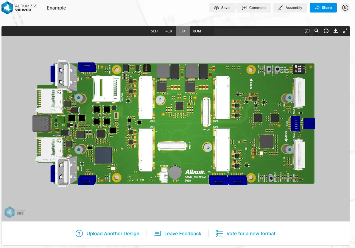
An example design project is included so that you can take the Altium 365 Viewer for a test drive straight away – just click the ![]() control.
control.

What Can I Upload?
The following sections summarize what can be uploaded to the standalone Altium 365 Viewer.
CAD Designs
In terms of design files, the following CAD design tools are supported, along with the file formats that can be uploaded to Altium 365 Viewer:
-
Altium Designer – Schematic (*.SchDoc, *.Sch) and PCB (*.PcbDoc, *.Pcb) documents.
-
Autodesk® EAGLE™ – Schematic design archive (*.sch) and PCB design archive (*.brd) documents.
-
KiCad® – Project file (*.pro), Schematic document(*.sch), PCB document (*.kicad_pcb,) and Schematic Symbols Library (*.lib).
-
CircuitStudio – Schematic (*.SchDoc) and PCB (*.CSPcbDoc) documents.
CAD Data Upload Considerations
You can upload a full design (in a Zip, Rar, or 7z, or Tgz archive) or an individual design file (schematic or PCB document). When uploading an archive file, the following considerations apply:
- For Altium Designer and CircuitStudio based designs, the archive must contain a single PCB design project only.
- For EAGLE based designs, the archive must contain a single PCB design only (so .sch and .brd files for a single design only).
- For KiCad based designs, the Zip archive must contain a single PCB design only (so .pro , .sch , .kicad_pcb, and .lib files for a single design only).
- All unsupported file formats in the uploaded archive will be ignored, which means you can literally just Zip, Rar, or 7z your full project folder and upload it.
CAM Data
In terms of CAM (manufacturing), the following formats are supported for upload to Altium 365 Viewer:
-
Gerber X2 (along with corresponding NC Drill files).
-
Gerber RS-274X (along with corresponding NC Drill files).
-
ODB++ fileset.
CAM Data Upload Considerations
You can upload a full set of ODB++ or Gerber files, their archived fileset (Zip, Rar, 7z, Tgz), or even an individual Gerber file. When uploading a Gerber CAM archive file, the following considerations apply:
-
Ensure that there is only a single folder of Gerbers inside the archive.
-
Ensure that the drill files are in the same folder as the Gerber files. If located in a separate folder, they will be ignored.
Performing the Upload
Data can be uploaded by:
- Dragging and dropping your CAD design or archived CAM data (Zip, Rar, 7z, Tgz), or an individual design/manufacturing file, to the indicated area on the Home page.
-
Clicking the
 button (in the upload area on the Home page) or the Upload Files control (at the top-right of the Home page) and using the Open dialog that appears to browse for the archived CAD design or CAM data, or an individual design/manufacturing file.
 button will be provided in the banner at the top of the page.
With an archive or individual file chosen (or dropped), the main viewing area will reflect that the upload is in progress. The processing time will depend on the size of the data being uploaded. If the upload fails – typically because a single file is uploaded that is in a non-supported format – the main viewing area will reflect this also.


 control, below the main viewing window. To upload into a separate viewer tab, click the
  control at the bottom-left of the main viewing area.
Sharing Your Design
When you upload a CAD design (or CAM data) to Altium 365 Viewer on the Altium website, that design/data is available for the duration of your browser session. Should you wish to share the design/data with others, you can do so by clicking the  button, located at the top-right of the main viewing window. A window will be presented containing a link to the design/data. Copy (
 ) and share it with others as required – the link will remain active for a period of 48 hours.
 with others – time limited to 48 hours.") Obtain a link with which to share your uploaded CAD design (or CAM data) with others – time limited to 48 hours.
Obtain a link with which to share your uploaded CAD design (or CAM data) with others – time limited to 48 hours.
When the link is used to access the design/data, a temporary pop-up will appear at the top of the browser window, alerting you to the time left before the link expires.
 Those using a shared link will be notified on entry how long is left before the link expires. In this example, 47 hours left to view shared design data.
Saving Uploaded Data to Your Altium 365 Personal Space
Being able to upload and view data during your browser session is good. Being able to share a link to that data for 48 hours is better. But by far the best approach would be to have that data permanently stored and available to share with others whenever you like. And not just for viewing, but also for commenting and redlining too. This is where an Altium 365 Personal Space comes in. As its name suggests, a Personal Space is a dedicated area on the Altium 365 infrastructure platform, which is accessible only to you. Your Personal Space accommodates persistent storage of various types of uploaded static data and is completely free – ideal for those who want to experience the collaborative aspect of Altium 365, without the need for a connected Altium 365 Workspace in which to store their data.
The data that you have uploaded to the standalone Altium 365 Viewer can be saved to your Personal Space. To do so, click the ![]() button, located at the top-right of the main viewing window, or the
button, located at the top-right of the main viewing window, or the  button then
  option. If you are already signed in to an Altium Account , you will be taken to your Personal Space on Altium 365 and the data uploaded there. If you are not currently signed in to an Altium Account, you'll be taken to the Altium 365 Sign In page, with which to do so first.Assembly
Once the data is uploaded to your Personal Space you will be taken to it directly – presented using Altium 365's Web Viewer interface. In the Files page of your Personal Space, you can view all of your uploads, share with others and upload more – with a more powerful interface that also provides a gateway to the advanced features offered by the Altium 365 Platform.


 control at the top-right of the page to access the Altium 365 Sign In page with which to do so (or to register for an account). If you are signed in, this control will present as your photo/picture (or generic icon with the first letter of your name, e.g.
  ).
).Embedding Altium 365 Viewer on Your Own Website
Related page: Altium 365 Personal Space – Embedding Uploaded Data on a Website
Altium 365 Viewer can be embedded on your own website, which allows you to share an uploaded CAD design (or CAM data) with your readership. The embedded Viewer will remain active for as long as the source design files are available, which in the case of files uploaded to the Altium 365 online Viewer is 48 hours. If you use a custom viewer code that references design files hosted on your own website, the embedded viewer will have a permanent source and therefore remain active.
The Altium 365 Viewer is ideal for showcasing a development or evaluation board, and by having an interactive platform for your designs, your users can see and get a real feel for the design in a way they couldn't with a standard datasheet or static block diagram.
The following examples show third parties who have embraced and embedded Altium 365 Viewer on their own websites:
-
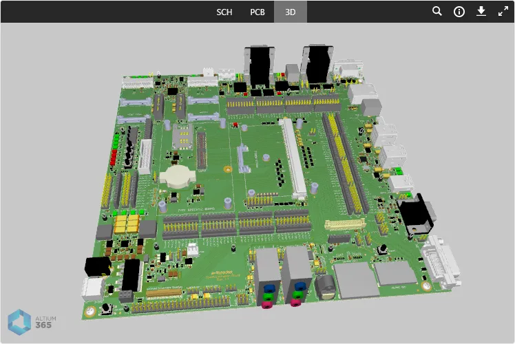
An example showing Altium 365 Viewer embedded on the Toradex® website for their Apalis Evaluation Board.

-
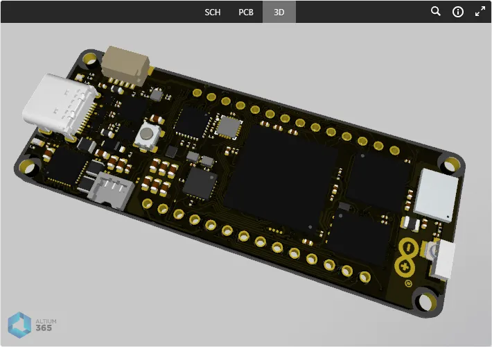
An example showing Altium 365 Viewer embedded on the Arduino® website for their Portenta H7 Board.

- An example showing Altium 365 Viewer embedded on a GitHub® page.
 Example showing Altium 365 Viewer embedded on a page within the GitHub community.
Obtaining Embed Code from the Altium Website
When you upload a CAD design or CAM data to Altium 365 Viewer, you also have the opportunity to get the embed code for that design/data – to embed that specific design/data into your own website. To do so, click the button, located above the top-right of the main viewing window. The Share <project> window will appear, from where you can copy the code elements for pasting into your own web page (Copy Code) – ensure that the <script> code is included along with the <div> section.
 Accessing the embed code for a design uploaded to Altium 365 Viewer on the Altium website.
Select the Embed this design anywhere in the web tile in Viewer's Share window to preview the Embedded HTML code, and then Show Options to access its view settings. The Include views and Default view options you choose are incorporated directly in the available HTML code.

Custom Embedded Code
In the same way as outlined above, an Altium 365 Viewer that references your own design files can be embedded on any web page by placing the Javascript reference and DIV section in the HTML page source. The enabling Javascript code is ideally placed in the <head> section of the webpage, but for convenience can be included after the DIV section:
<script src="https://viewer.altium.com/client/static/js/embed.js"></script>
The DIV code section attaches event listeners used to initialize and style the embedded viewer on your page. In this case, data-project-src is used to specify your own design zip file (mydesign.zip):
<div class="altium-ecad-viewer"
  data-project-src="http:∕∕example.com/mydesign.zip"
  style="border-radius: 0px 0px 4px 4px; height: 500px;

    border-color: rgb(241, 241, 241);
    overflow: hidden; max-width: 1280px;
    max-height: 700px; box-sizing: border-box;">
  <a href="https://www.altium365.com/viewer/">PCB File Viewer by Altium</a>
</div>
Note:
-
class="altium-ecad-viewer" – this must not be changed, as it is used by the event listeners.
-
data-project-src – this is the link to the design or manufacturing data you want to display. This link should be a public link containing a Zip, Rar, or 7z archive with your PCB project or manufacturing data files.
-
style – this can be changed as required to suit your presentation preferences.
-
The basic embedded code's structure can be obtained from the Embed window available from the Altium 365 Website Viewer, as outlined above, and then modified to suit your needs.
Controlling Active and Enabled Views
The following two attributes determine which data views are enabled, and which data view is the default active view:
-
data-enabled-views – defines the visibility of the various supported data views. Supported and default values are sch (SCH data view), pcb (PCB data view), 3d (3D data view), and bom (BOM data view). When this attribute is not included in the embedded code, the default value is used: sch,pcb,3d,bom.
Note: Values are case insensitive. Multiple values must be separated by a comma (,). You cannot have only the BOM view enabled by itself. -
data-active-view – defines which data view is to be active when your embedded Altium 365 Viewer is first accessed. Supported values are sch (SCH data view), pcb (PCB data view), and 3d (3D data view). When this attribute is not included in the embedded code, the default value is used: sch.
Note: Values are case insensitive. Only one value can be set for this attribute. The chosen active view must also be an enabled view.
The following are examples of using these attributes:
Example 1
<div class="altium-ecad-viewer"
  data-project-src="http:∕∕example.com/mydesign.zip"
  data-enabled-views='pcb,3d'
  data-active-view='pcb'
  style="border-radius: 0px 0px 4px 4px; height: 500px;

         border-color: rgb(241, 241, 241);
         overflow: hidden; max-width: 1280px;
         max-height: 700px; box-sizing: border-box;">
  <a href="https://www.altium365.com/viewer/">PCB File Viewer by Altium</a>
</div>
Here, only the PCB and 3D data views will be presented. The PCB data view will be the active view when Altium 365 Viewer is first accessed.
Example 2
<div class="altium-ecad-viewer"
  data-project-src="http:∕∕example.com/mydesign.zip"
  data-enabled-views='sch,bom'
  style="border-radius: 0px 0px 4px 4px; height: 500px;

         border-color: rgb(241, 241, 241);
         overflow: hidden; max-width: 1280px;
         max-height: 700px; box-sizing: border-box;">
  <a href="https://www.altium365.com/viewer/">PCB File Viewer by Altium</a>
</div>
Here, only SCH and BOM data views will be presented (the latter only if BOM data exists). Since the data-active-view attribute is not included, its default will be used – displaying the SCH data view when Altium 365 Viewer is first accessed.
Example 3
<div class="altium-ecad-viewer"
  data-project-src="http:∕∕example.com/mydesign.zip"
  data-enabled-views='3D'
  data-active-view='3D'
  style="border-radius: 0px 0px 4px 4px; height: 500px;

         border-color: rgb(241, 241, 241);
         overflow: hidden; max-width: 1280px;
         max-height: 700px; box-sizing: border-box;">
  <a href="https://www.altium365.com/viewer/">PCB File Viewer by Altium</a>
</div>
Here, only the 3D data view will be presented, and is therefore necessarily set as the active view when Altium 365 Viewer is first accessed.
Other Customizations
When adding the Altium 365 Viewer embedded code in your own website, you can optionally specify the type of source data that can be presented and what design outputs are available for download. See the collapsed sections below for detailed information.
Controlling Access to CAD and CAM Data
Controlling the available data types is achieved using the following attribute:
- data-src-type – defines what type of data can be viewed. Supported values are Design (CAD design projects only) and Gerber (CAM data only). When this attribute is not included in the embedded code, the default value is used: Design,Gerber.
The following are examples of using this attribute:
Example 1
<div class="altium-ecad-viewer"
  data-project-src="http:∕∕example.com/mydesign.zip"
  style="border-radius: 0px 0px 4px 4px; height: 500px;

         border-color: rgb(241, 241, 241);
         overflow: hidden; max-width: 1280px;
         max-height: 700px; box-sizing: border-box;">
  <a href="https://www.altium365.com/viewer/">PCB File Viewer by Altium</a>
</div>
Here, since the data-src-type attribute is not specified, both CAD designs and CAM data are supported by the embedded Altium 365 Viewer. Therefore the link specified in the data-project-src attribute can be a public link containing a Zip, Rar, or 7z archive with either a PCB project or manufacturing (CAM) data files.
Example 2
<div class="altium-ecad-viewer"
  data-project-src="http:∕∕example.com/mydesign.zip"
  data-src-type='Design'
  style="border-radius: 0px 0px 4px 4px; height: 500px;

         border-color: rgb(241, 241, 241);
         overflow: hidden; max-width: 1280px;
         max-height: 700px; box-sizing: border-box;">
  <a href="https://www.altium365.com/viewer/">PCB File Viewer by Altium</a>
</div>
Here, only CAD designs are supported by the embedded Altium 365 Viewer. Therefore the link specified in the data-project-src attribute must be a public link containing a Zip, Rar, or 7z archive with a PCB project.
Example 3
<div class="altium-ecad-viewer"
  data-project-src="http:∕∕example.com/mycamdata.zip"
  data-src-type='Gerber'
  style="border-radius: 0px 0px 4px 4px; height: 500px;

         border-color: rgb(241, 241, 241);
         overflow: hidden; max-width: 1280px;
         max-height: 700px; box-sizing: border-box;">
  <a href="https://www.altium365.com/viewer/">PCB File Viewer by Altium</a>
</div>
Here, only CAM data is supported by the embedded Altium 365 Viewer. Therefore the link specified in the data-project-src attribute must be a public link containing a Zip, Rar, or 7z archive with manufacturing data files.
Controlling Downloads
When you embed Altium 365 Viewer on your own website, extra functionality is provided to generate and download a number of different outputs from your uploaded design. For more information, refer to the section on Downloads. You can determine, through the following attributes, what can be downloaded, and therefore what appears on the Downloads pane.
-
data-hide-project-src – use of this attribute disables the ability to download the original source design, as otherwise listed in the pane as
Altium Designer. It has no parametric values. - data-project-src-alternative – this attribute is used when you want the design that a person can download to be different to the original uploaded source design. Its value is a link to a publicly available Zip, Rar, or 7z archive.
-
data-project-outputs – defines the outputs that will be generated from your uploaded project and made available for download. Supported values are Gerber, Idf, Ipc2581, Odb, Step and Pdf. When this attribute is not included in the embedded code, all supported outputs will be generated. If the attribute is included with a value of
noneor no values are defined, then all supported outputs will be disabled.
Note: Values are case insensitive. Multiple values must be separated by a comma (,).
Example 1
<div class="altium-ecad-viewer"
  data-hide-project-src
  data-project-src="http:∕∕example.com/mydesign.zip"
  style="border-radius: 0px 0px 4px 4px; height: 500px;

         border-color: rgb(241, 241, 241);
         overflow: hidden; max-width: 1280px;
         max-height: 700px; box-sizing: border-box;">
  <a href="https://www.altium365.com/viewer/">PCB File Viewer by Altium</a>
</div>
Here, the user will not be able to download the original source design, but all supported outputs will be generated and available for download through the Downloads pane.
Example 2
<div class="altium-ecad-viewer"
  data-project-src="http:∕∕example.com/mydesign.zip"
  data-project-src-alternative="http:∕∕example.com/myalternativedesign.zip"
  style="border-radius: 0px 0px 4px 4px; height: 500px;

         border-color: rgb(241, 241, 241);
         overflow: hidden; max-width: 1280px;
         max-height: 700px; box-sizing: border-box;">
  <a href="https://www.altium365.com/viewer/">PCB File Viewer by Altium</a>
</div>
Here, the user will be able to download an alternative design from the Downloads pane, along with all supported outputs.
Example 3
<div class="altium-ecad-viewer"
  data-project-src="http:∕∕example.com/mydesign.zip"
  data-project-src-alternative="http:∕∕example.com/myalternativedesign.zip"
  data-project-outputs='Gerber,odb,pdf'
  style="border-radius: 0px 0px 4px 4px; height: 500px;

         border-color: rgb(241, 241, 241);
         overflow: hidden; max-width: 1280px;
         max-height: 700px; box-sizing: border-box;">
  <a href="https://www.altium365.com/viewer/">PCB File Viewer by Altium</a>
</div>
Here, the user will be able to download an alternative design from the Downloads pane. Of the supported outputs, only Gerber, ODB++ and PDF will be generated and available for download.
Working with an Uploaded Design
Once your design (or single file) is uploaded, you can browse it. The following sections take a detailed look at the various features and functionality Altium 365 Viewer provides to facilitate this. Full functionality is, of course, best enjoyed by having a full design uploaded.
Data Views
Altium 365 Viewer presents your uploaded design across four distinct data views, to show the source schematic(s), board in 2D, board in 3D, and Bill of Materials respectively. Each data view will only be shown if there is a corresponding uploaded document to do so.
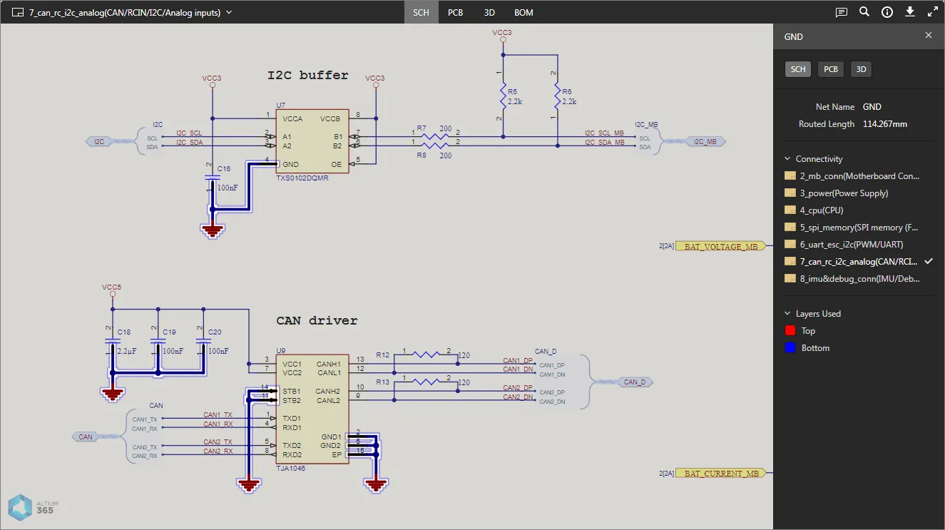
SCH
This view presents the source schematic sheet(s) for the design.
 The SCH data view presents the currently selected schematic source document.
Switching Schematics
If more than one schematic sheet exists as part of the uploaded design, a full listing of the documents can be accessed by clicking on the control at the top-left of the view. Each document is presented as a preview – click on an entry to make it the active document. The currently selected document – the active document being viewed within the SCH data view – is distinguished in the list with a blue border around its entry.
 Browse all uploaded schematics – click an entry to make it the active document.
Support for Multi-channel Designs
Altium 365 Viewer supports viewing of multi-channel designs. A separate schematic document is presented for each physical channel. The physical sheet name – the compiled tab for that schematic document when viewed through Altium Designer – is included as a suffix to the document name. The result is similar to generating a PDF document of the physical schematic sheets, only with the enhanced interaction that Altium 365 Viewer brings.
 Example multi-channel design, with each physical channel being presented on a different schematic sheet.
Browsing Controls
Browsing controls for the main viewing window are as follows:
- Mouse wheel forwards/backwards to zoom in/out.
- Click & hold (or right-click & hold), then drag to pan document.
- Click to select.
- Press R to reset the view of the document (to show entire document).
PCB
This view presents the PCB in 2D.
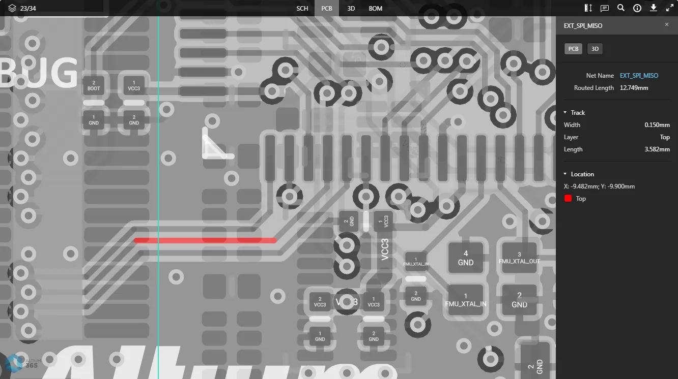
 The PCB data view presents a 2D view of the PCB.
Browsing Controls
Browsing controls for the main viewing window are as follows:
- Mouse wheel forwards/backwards to zoom in/out.
- Click & hold (or right-click & hold), then drag to pan document.
- Click to select. Click repeatedly to cycle through collocated objects and/or to select the parent net.
- Press + or – on the numeric keypad to step forward or back through the list of layers, in single layer mode.
- Press R to reset the view of the document (to show entire document).
Controlling Layer Visibility
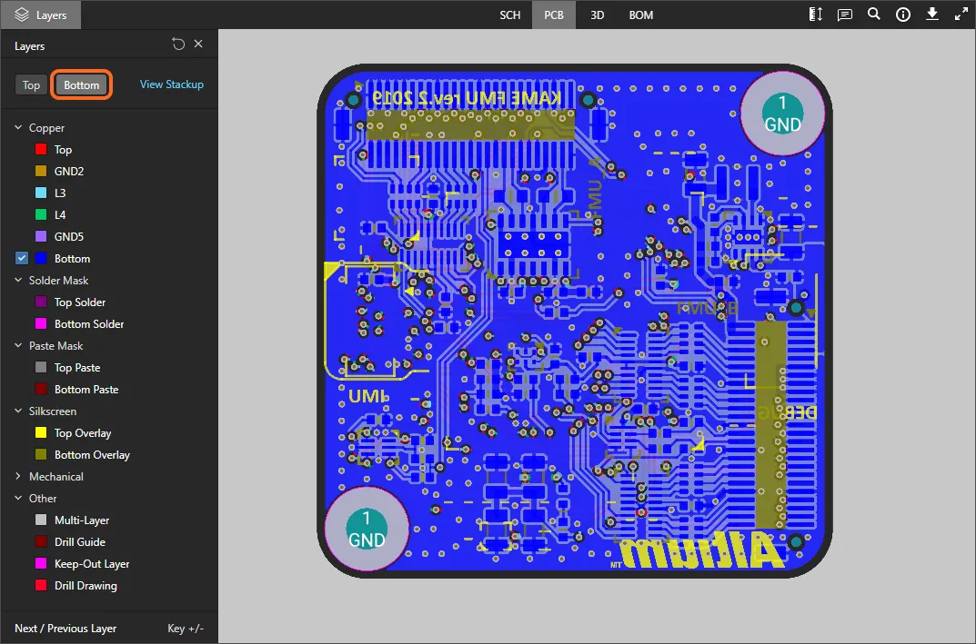
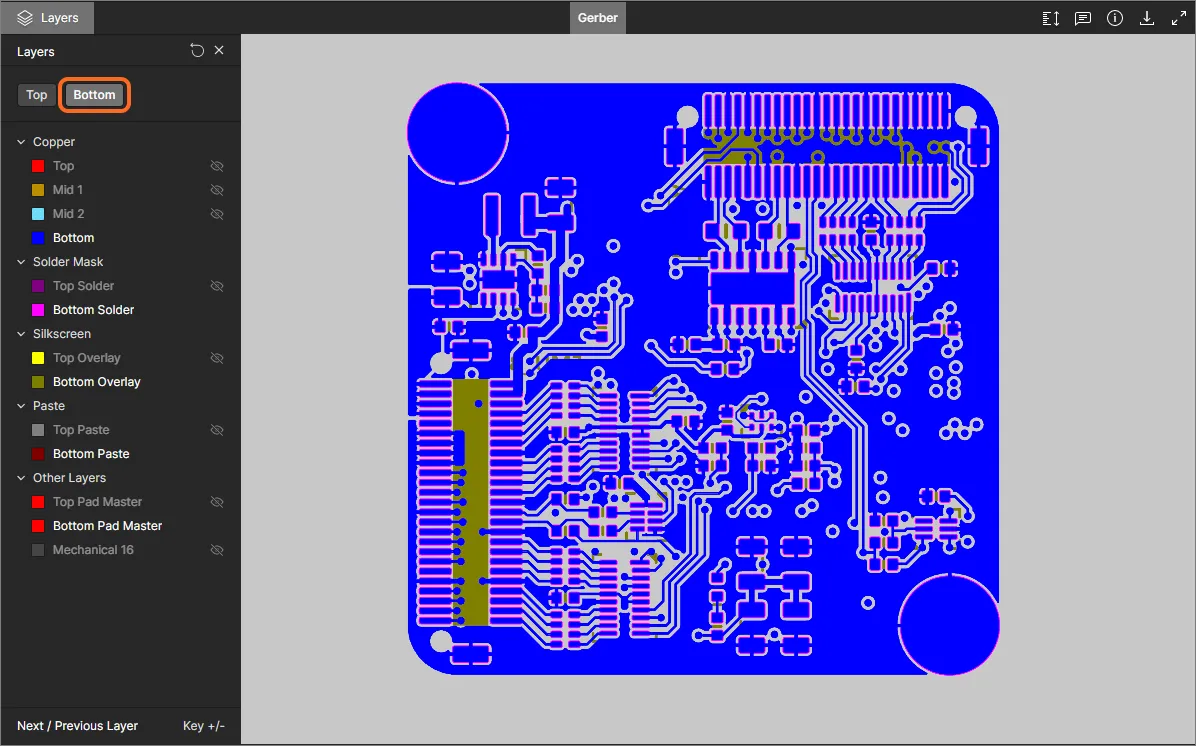
Control over the view and layer visibility for the PCB data view is performed through the Layers pane. Access this pane by clicking on the  control at the top-left of the view.
 Layers pane – command central for controlling layer visibility.
Each layer entry listed in the Layers pane has an associated checkbox that sets it to the top of the graphical draw order. When checked, that layer will be rendered last so that it effectively overlays the other PCB layer graphics. A placed Comment will be associated with the currently selected (checked) layer, and that same layer order is restored when the Comment is subsequently selected in the Comments pane.
When the layer order view has been reset (using the ![]() control at the top) the draw order reverts to its default condition (Top layer).
control at the top) the draw order reverts to its default condition (Top layer).

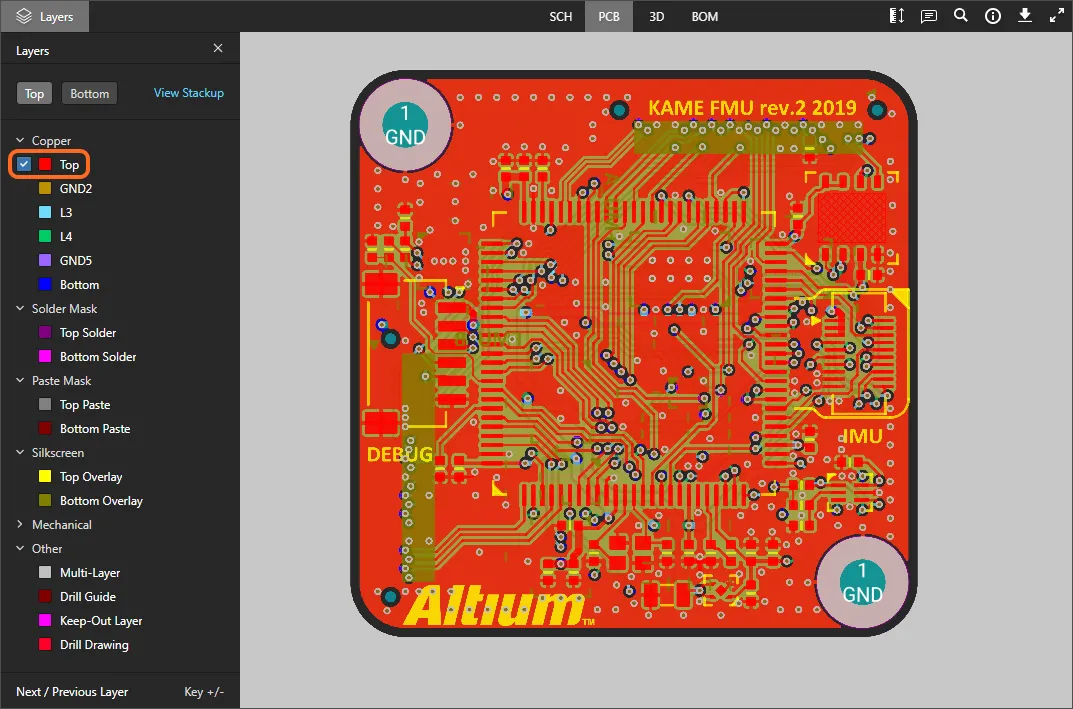
The pane's layer entries are grouped into the following categories:
- Copper – all used signal and internal plane layers.
- Solder Mask – Top Solder, Bottom Solder.
- Paste Mask – Top Paste, Bottom Paste.
- Silkscreen – Top Overlay, Bottom Overlay.
- Mechanical – all used mechanical layers.
- Other – including Mutli-Layer, Drill Guide, Keep-Out Layer and Drill Drawing.
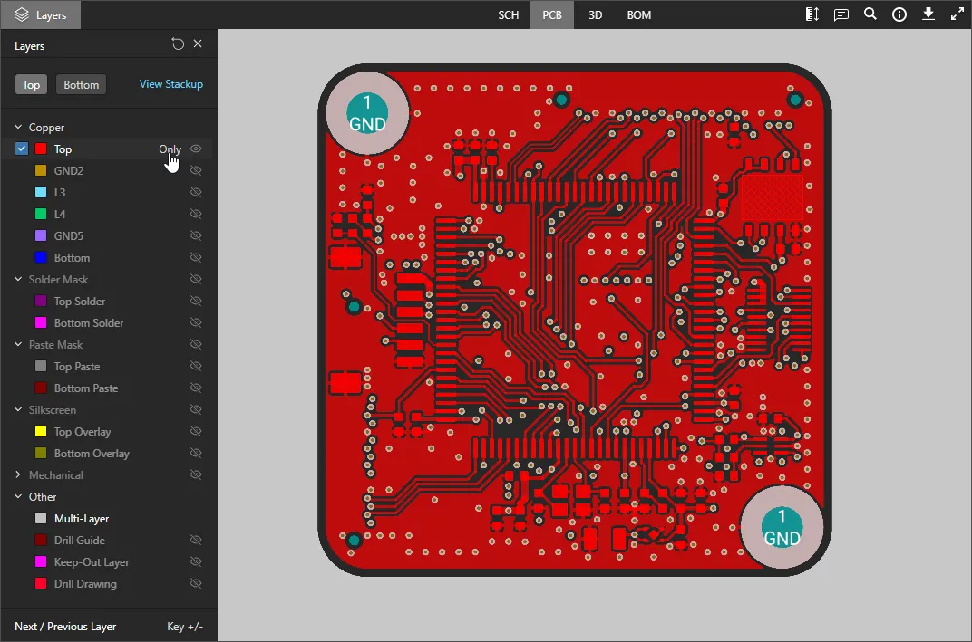
Use the Top and Bottom view controls at the top of the pane to quickly toggle between viewing the board from the top or bottom respectively, and if desired, change the top draw order to suit using the layer entry checkboxes.

The following points relate to working with layer visibility in the Layers pane:
-
A currently visible layer is shown in the pane undimmed (e.g.
 ). A currently hidden layer is shown in the pane with its name dimmed (e.g.
  ), along with the
  icon displayed at its far right.
-
A currently visible layer can be hidden by clicking on its entry, or by hovering over its entry and clicking the
 icon at its far right. Conversely, a currently hidden layer can be made visible by clicking on its entry, or by hovering over its entry and clicking the icon at its far right.
-
An entire group of layers can be hidden by hovering over the group entry and clicking the icon at its far right. Conversely, if all layers in a grouping are currently hidden, they can be made visible by hovering over the group entry and clicking the icon at its far right. Note that if a group has a mixture of visible/hidden layers, the icon will be present for the group. Click to hide all other layers, then click again (now showing as ) to make all layers visible.
-
To quickly view in 'Single Layer Mode', hover over the specific layer of interest, then click the
 control. All other layers will be hidden. Click the control again to come out of 'Single Layer Mode'.

-
To reset layer visibility back to how it was when the design was initially uploaded, click the
 control at the top-right of the Layers pane.
Taking Measurements
When viewing the board in 2D – using the PCB data view – you are able to take measurements. To do so click the ![]() button. The Measurements pane opens, the cursor changes to a cross-hair, and you will enter measurement mode. Three measurement modes are supported:
button. The Measurements pane opens, the cursor changes to a cross-hair, and you will enter measurement mode. Three measurement modes are supported:
- Free – freely measure between any two points within the data view, without any snapping guidance whatsoever.
- Point to Point – measure between any two points within the data view, with guidance snapping as you move the cursor over an object. The cursor will change as follows:
-
 – the center of a pad or via.
-
 – the vertex point of a primitive object.
-
 – the mid-point of a track segment.
-
 – a free point within the view.
- Object to Object – measure between any two chosen objects within the data view. Supported objects are pad, via, track, fill and region, which will become highlighted for selection as you move the cursor over them.
Measurement is performed as follows:
- In Free or Point to Point modes, position the cursor to where you wish to start measuring (Point 1) and click. The point is marked using a small white cross. In Object to Object mode, choose the first object (Object 1), which will become selected.
- In Free or Point to Point modes, move the cursor to the required end point (Point 2) and click again. As you move the cursor, a measuring line is displayed as an aide, showing the current XY distance (from Point 1 to the end of the line). In Object to Object mode, choose the second object (Object 2), which will become selected.
- The Measurements pane reports the XY distance measured, the X (horizontal) distance, and the Y (vertical) distance. For the Object to Object mode, the XY distance will be the shortest point between the two chosen objects.
-
Continue measuring the distance between other points or objects, or click the
 button again (or Esc) to exit measurement mode.
 Example measurement taken in Object to Object mode.
Inspecting the Board Layer Stackup
The Layer Stackup view presents an interactive graphical representation of the PCB's physical layer stack, along with information on individual layers and the overall stack. The view is accessed from the Information pane (![]() ) by selecting the Stackup View option associated with the Layers section, or by using the Stackup View option in the Layers selector drop-down menu.
) by selecting the Stackup View option associated with the Layers section, or by using the Stackup View option in the Layers selector drop-down menu.

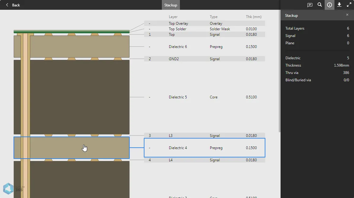
Each Layer Stack element in the view is selectable, including Vias. The Information (Layers) pane is populated with data corresponding to the currently selected layer/via, or shows a summary of the overall Stackup if a stack element is not selected. Like other design views, Comments can be placed on the Layer Stackup view.
► See the Web Viewer Layer Stack View for more information.
3D
This view presents the PCB in 3D.
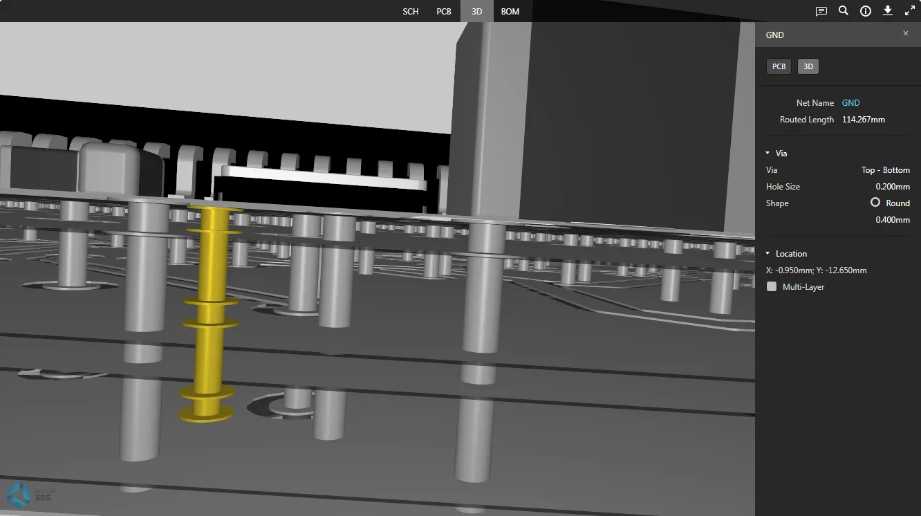
 The 3D data view presents a 3D view of the PCB.
Browsing Controls
Browsing controls for the main viewing window are as follows:
- Mouse wheel forwards/backwards to zoom in/out.
- Click & hold, then drag to rotate the board.
- Right-click & hold, then drag to pan document.
- Click to select.
- Press R to reset the view of the document (to show entire document).
BOM
This view presents the Bill of Materials for the design. This is built on-the-fly from the source schematic documents – for an Altium Designer design, an ActiveBOM document (*.BomDoc) is neither required, nor used by Altium 365 Viewer.
 The BOM data view presents the Bill of Materials for the design – created on-the-fly from the source schematics.
The BOM reflects all components required to assemble a single board. Pricing information is sourced from Octopart.
The following points relate to working with the view:
- Clicking on the Name entry for a component will access the page for the corresponding real-world part on the Octopart site (opens in a separate tab).
- Clicking on a designator will cross-probe to that component on the other data views.
- You can sort by Name, Price, or Quantity – click a header once to sort in ascending order. Click again to sort in descending order.
- Use the Search field above the listing to quickly find a component of interest. Search applies across Name, Price, Description and Designator fields.
Common Interface Elements
The following controls (located in the top-right control cluster) are common to various data views:
-
 – opens the Comments pane, which allows you to place textural notes on a design data view. Comments can be associated with a specific element, area or location on a view, and are collectively accessed through the Comments pane. Note that unlike in the more advanced Altium 365 viewer platfoms, the Standalone Web Viewer's comments are not saved, or available when the design is shared.
► See Web Viewer Comments for more information. -
 – use this control to access the Search facility, allowing you to search for components and/or nets. This facility is available for the SCH, PCB and 3D data views (the BOM data view has its own search). For more information on using the search facility, see Searching.

-
 – use this control to access the Info pane.

The pane is further divided into two sub-views:
- Controls – gives a helpful listing of controls when browsing the SCH, PCB and 3D data views (some controls are view-specific).
- Board Info – gives useful summary information about the uploaded design in terms of: Board Size (X and Y dimensions of the board); Layers (total Signal + Plane as well as counts for each); Components (total, including all types of component, with a breakdown of those components on Top and Bottom of the board); Nets (total). Note that the Layers section includes a command link to the Layer Stackup view.
-
 – provides access to the Downloads pane, which offers a preview of the data download capabilities provided by the more advanced Altium 365 viewers. Note that downloads are functional when you embed the viewer on your own website.
► See Web Viewer Downloading for more information. -
 – use this control to switch to Full Screen mode.
-
 – when in Full Screen mode, use this control to exit Full Screen mode (or press Esc).
Selection
Selection of an object within the design can be performed from the SCH, PCB and 3D data views as follows:
-
From the SCH data view (component and net selection) – hover the cursor over a component or wire and click to select. Masking is applied to leave only that component or net fully visible. Information for the selected component/net will appear in the right-hand pane.

-
From the PCB data view (component, pad, via, track segment and net selection) – hover the cursor over a supported object type and click to select. Masking is applied to leave only that object fully visible. Information for the selected object will appear in the right-hand pane.

-
From the 3D data view (component, pad, via selection) – hover the cursor over a component, pad, or via and click to select. Masking is applied to leave only that object fully visible. Information for the selected object will appear in the right-hand pane.

Cross-probing
When you select a supported object within the active data view, that object is selected (where applicable) on one or more other data views as well – enabling you to quickly cross-probe to that same selection. Cross-probing support is conveniently delivered through controls located at the top of the right-hand pane – displayed when an object is currently selected in the main viewing window.
.") Cross-probing controls (for a selected component).
Cross-probing controls (for a selected component).
The following collapsible sections present a few examples of supported cross-probing scenarios:
Cross-probing a Component from the SCH/PCB/3D Data View
Select the required component in the active data view, then click one of the buttons to cross-probe to that component in the target data view. For SCH, PCB and 3D data views (accessed by clicking the SCH, PCB, or 3D controls), the component will be selected and zoomed within the view where possible, and masking applied to leave only the selected component fully visible.


For the BOM data view (accessed by clicking the BOM control), the row entry for the component will be highlighted.

Cross-probing a Component from the BOM Data View
Click on the designator for the component you wish to cross-probe to. The last active data view prior to accessing the BOM data view will be made active, with the component selected, centered and zoomed within the view where possible, and masking applied to leave only the selected component fully visible. From there, you can use the controls (SCH, PCB, 3D and BOM) to cross-probe to that selected component in other data views as described previously.

Cross-probing a Net from the SCH Data View
Select the required net on the schematic document within the SCH data view, then click one of the controls (PCB, 3D) to cross-probe to that net in the target data view. The net will be selected and zoomed within the view where possible, and masking applied to leave only the selected net fully visible.


Cross-probing a Pad/Via/Track from the PCB Data View
Select the required pad, via, or track segment on the board within the PCB data view, then click the 3D control to cross-probe to that pad/via/track segment in the 3D data view. The object will be selected and zoomed within the view where possible, and masking applied to leave only the selected object fully visible.


Searching
Altium 365 Viewer incorporates a search facility that provides a quick and convenient way to locate components and nets throughout your uploaded design. The search feature can be accessed from the SCH, PCB and 3D data views by clicking the ![]() button, at the top-right of the view. A Search pane will be presented in which to conduct the search.
button, at the top-right of the view. A Search pane will be presented in which to conduct the search.
 Altium 365 Viewer's Search pane.
To perform a search, start typing your search string. Search is case-insensitive. The pane lists the matching results dynamically as you type. The number of matching results is highlighted at the top of the pane.
 button, or press Enter (with the cursor in the search field).
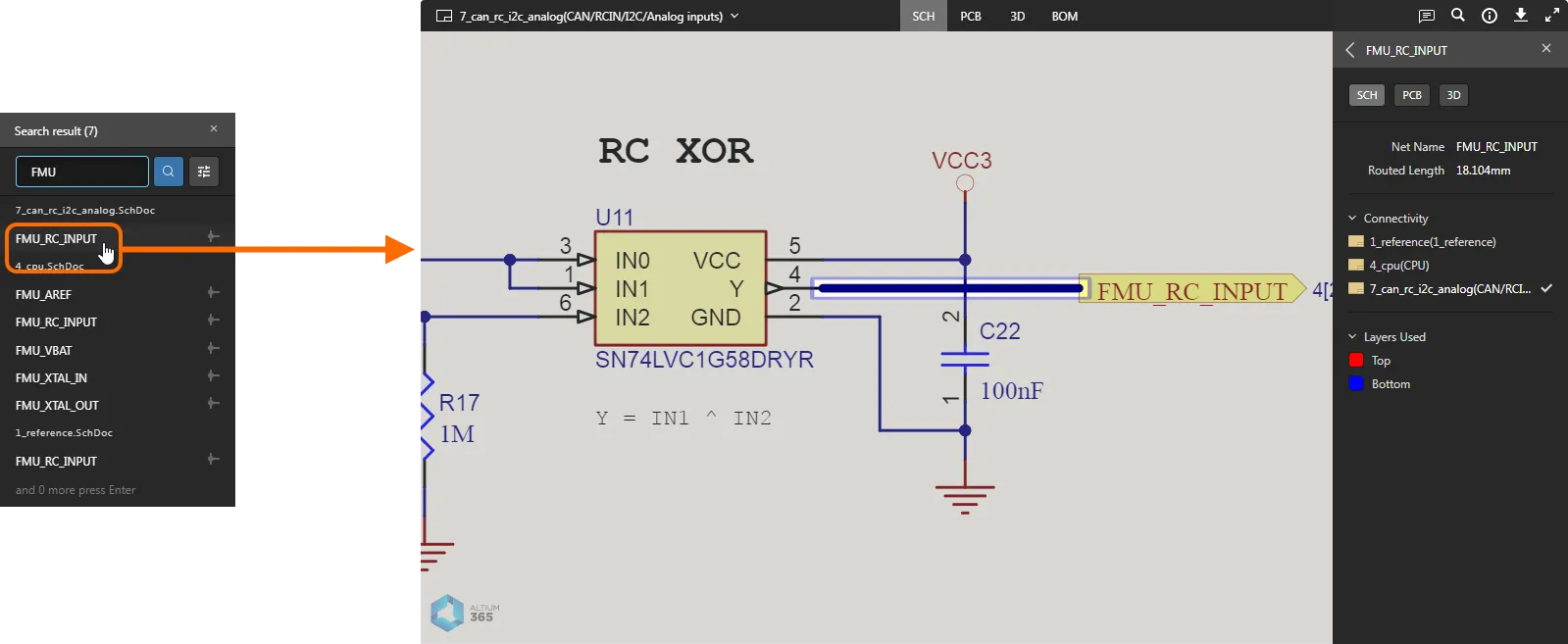
 Example search conducted from the SCH data view.
Click the  button to access filter options, to show all components and nets matching the search string, or just components, or just nets.
 Filter controls.
With search results listed, click an entry to navigate to that entity – component or net – within the active data view. The component/net will be selected and zoomed within the view where possible, and masking applied to leave only the selected component/net fully visible.

The search facility is great for finding and selecting a net on the 3D view of the board – something that cannot be done by simple selection alone, since you can only click to select components, pads and vias in the 3D data view.
 Example result of searching for a net within the active 3D data view – the only way, aside from cross-probing, to select a net within this view.
Downloads – Embedded Altium 365 Viewer only
When you embed Altium 365 Viewer on your own website, extra functionality is provided to generate and download a number of different outputs from your uploaded design. Currently supported output formats are:
- The source design
- Gerber
- IDFX
- IPC2581
- ODB++
- STEP
- PDF – comprising individual PDFs for Schematic Prints, PCB Prints, PCB 3D Print and PDF 3D.
To download data, click the ![]() control, at the top-left of the main viewing window. A Downloads pane will be presented, listing the files available. Enable the files that you want to download and then click the
control, at the top-left of the main viewing window. A Downloads pane will be presented, listing the files available. Enable the files that you want to download and then click the  button.
 and the downloads available for the design.") Example embedded Altium 365 Viewer (on the Toradex site) and the downloads available for the design.
Example embedded Altium 365 Viewer (on the Toradex site) and the downloads available for the design.
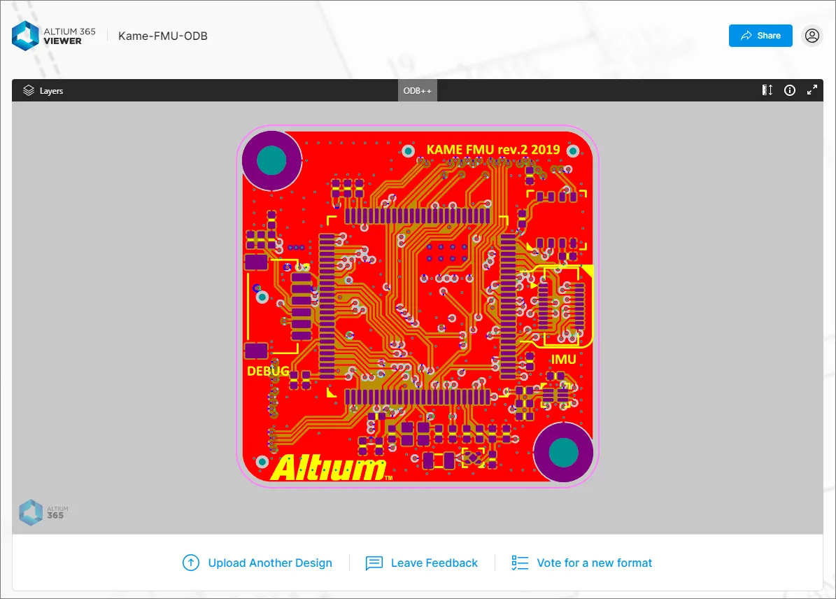
Working with Uploaded Manufacturing Data
Once your set of ODB++ or Gerber data (or a single Gerber file) is uploaded, you can browse it. A single view of your data is provided – the Gerber/ODB++ data view.
 button (available with Gerber data only) provides a direct link to the

Browsing Controls
Browsing controls for the main viewing window are as follows:
- Mouse wheel forwards/backwards to zoom in/out.
- Click & hold (or right-click & hold), then drag to pan document.
- Press + or – on the numeric keypad to step forward or back through the list of layers, in single layer mode.
- Press R to reset the view of the document (to show entire document).
Controlling Layer Visibility
Control over the view and layer visibility for the CAM data view (Gerber or ODB++) is performed through the Layers pane. Access this pane by clicking on the control at the top-left of the view.
 Layers pane – command central for controlling layer visibility.
The pane's layer entries will reflect those included in the CAM data source. The layers are categorized into groups, which are typically:
- Copper – all used signal and internal plane layers.
- Solder Mask – Top Solder, Bottom Solder.
- Silkscreen – Top Overlay, Bottom Overlay.
- Paste – Top Paste, Bottom Paste.
- And a range of other layer types included in the Gerber or ODB++ set, such as Pad, Hole, and Mechanical data layers.
Use the Top and Bottom view controls at the top of the pane to toggle between viewing the Top or Bottom set of CAM layers respectively. Copper mid layers will be disabled in both cases.

The following points relate to working with layer visibility in the Layers pane:
-
A currently visible layer is shown in the pane undimmed (e.g.
). A currently hidden layer is shown in the pane with its name dimmed (e.g. ), along with the icon displayed at its far right.
-
A currently visible layer can be hidden by clicking on its entry, or by hovering over its entry and clicking the
icon at its far right. Conversely, a currently hidden layer can be made visible by clicking on its entry, or by hovering over its entry and clicking the icon at its far right.
-
An entire group of layers can be hidden by hovering over the group entry and clicking the
icon at its far right. Conversely, if all layers in a grouping are currently hidden, they can be made visible by hovering over the group entry and clicking the icon at its far right. Note that if a group has a mixture of visible/hidden layers, the icon will be present for the group. Click to hide all other layers, then click again (now showing as ) to make all layers visible.
-
To quickly view in 'Single Layer Mode', hover over the specific layer of interest, then click the
control. All other layers will be hidden. Click the control again to come out of 'Single Layer Mode'.
-
To reset layer visibility back to how it was when the CAM data was initially uploaded, click the
control at the top-right of the Layers pane.
Taking Measurements
When viewing Gerber data – using the Gerber data view – you are able to take measurements. To do so click the ![]() button. The Measurements pane opens, the cursor changes to a cross-hair, and you will enter measurement mode. Measurement is performed as follows:
button. The Measurements pane opens, the cursor changes to a cross-hair, and you will enter measurement mode. Measurement is performed as follows:
- Position the cursor to where you wish to start measuring (Point 1) and click. The point is marked using a small white cross.
- Move the cursor to the required end point (Point 2) and click again. As you move the cursor, a measuring line is displayed as an aide, showing the current XY distance (from Point 1 to the end of the line).
- The Measurements pane reports the XY distance measured, the X (horizontal) distance, and the Y (vertical) distance.
-
Continue measuring the distance between other points or click the
button again (or Esc) to exit measurement mode.
 Example measurement.
Additional Controls
The following controls are also available while browsing your uploaded manufacturing data:
-
– use this control to access the Info pane.

Use the Controls sub-view to remind yourself of the controls available when browsing your manufacturing data.
-
– use this control to switch to Full Screen mode.
-
– when in Full Screen mode, use this control to exit Full Screen mode (or press Esc).
Accessing and Using the Assembly Assistant
Related pages: Altium 365 Assembly Assistant, Altium 365 Personal Space
The Altium 365 Assembly Assistant is an online PCB assembly tool that allows you to easily track and check off the process of manually assembling a board design. It brings together your uploaded project's BOM data and 2D/3D assembly data in a single, interactive interface for analyzing and stepping through the assembly process.
Access to the Assembly Assistant is provided through the  option at the top of the Standalone Viewer page. When invoked, the Assembly command will save your uploaded project to your Altium 365 Personal Space and then directly open the associated Assembly Assistant application.

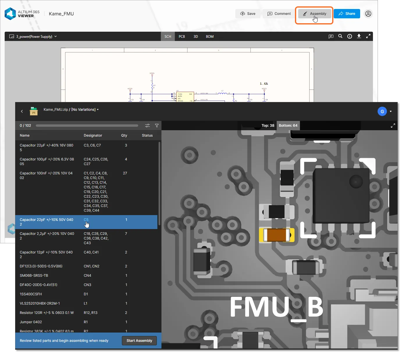
Comprised of a configurable BOM listing pane and an interactive graphical 2D/3D view of the board, the Assembly Assistant allows you to cross-probe between the two while inspecting either side of the board assembly. When in the assembly process mode ( ) the interface will step through and visually highlight each component entry, which can be confirmed as completed (
Done) or bypassed for later (Skipped). Once the process has been completed, the Assembly Assistant will report the number of placed elements and the elapsed time.
 The Assembly Assistant's active assembly process view showing Status settings and the dynamic interaction between the BOM entries and board graphics.