
The Print button opens the Print Preview dialog, which displays a preview of the current document that will be printed. The button is available in the Outputs | Documentation region of the schematic and PCB editors.

The Print Preview dialog allows you to view printouts and edit their setup definitions before actually printing.

Right-click Menu
The key commands available on the right-click menu of the top two regions are described below.
- Export Metafile - use this command to export the current preview as a Windows Enhanced Metafile (*.EMF).
- Page Setup - use this command to open a dialog to change printing properties of the current preview, such as paper size, scale and color.
- Print - use this command to open a dialog to configure printer options then print.
-
Setup Printer - use this command to open a dialog to configure printer properties.
- Configuration - use this command to open a print dialog to change advanced print properties, such as the layers and objects to be printed.
- Zoom In/Out - use to zoom in/out. Zooming can also be done by using the Ctrl+mouse wheel or the Page Up and Page Down keys. You can pan around the zoomed view by holding down the right-click mouse button then dragging the document. Use Shift+mouse wheel to scroll horizontally and the mouse wheel to scroll vertically.
Print Properties Dialogs
Properties Dialogs
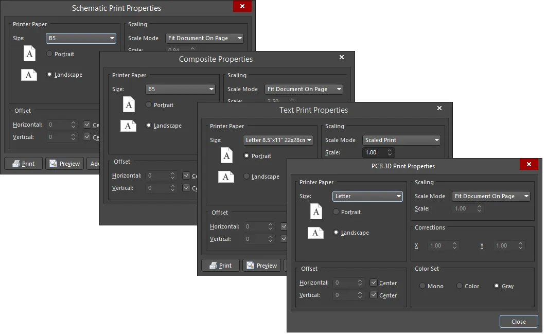
This dialog provides controls to configure the printout in terms of paper, scaling and color settings.
The dialog is accessed by right-clicking on a document in the Projects panel then choosing Page Setup or by right-clicking in the Print Preview dialog then choosing Page Setup. The PCB 3D Print Properties dialog is accessed by selecting Page setup for the PCB 3D Print output in the Generate Outputs dialog.
The key options are described below.
Offset
- Horizontal - use to manually adjust the position of the printed content on the page in the horizontal plane. Enter a positive value to shift the printed content to the right on the page or a negative value to shift it left. If the field is set to zero, the minimum horizontal left-hand margin required by the printer is used. Enable the Center option to automatically position the printed content so that it is centered horizontally on the page.
- Vertical - use to manually adjust the position of the printed content on the page in the vertical plane. Enter a positive value to shift the printed content upward on the page or a negative value to shift it downward. If the field is set to zero, the minimum vertical bottom margin required by the printer is used. Enable the Center option to automatically position the printed content so that it is centered vertically on the page.
Scaling
- Scale Mode - use the drop-down to select the mode of scaling desired.
- Scale - this field is available when Scale Mode is set to Scaled Print. Use it to define how much the document is scaled. Entering a value greater than 1 will essentially enlarge the print (a zoomed-in effect) while entering a value less than 1 will shrink it (a zoomed-out effect).
Where the print is enlarged, the true content of the original page is still printed; it will just be divided over a number of pages. These pages, when printed and placed together, will show the enlarged original printed content.
Corrections - the X/Y fields are available when Scale Mode is set to Scaled Print. Use these settings to adjust the printout in the horizontal and vertical planes for scaling errors in the printer.
Additional Controls
- Print - opens the Printer Configuration for dialog for confirmation of what is to be printed and to which printing device.
- Preview - opens the Print Preview dialog with the page(s) to be printed loaded and in accordance with the defined page setup and printer configuration. Use the preview to ensure the resulting print looks exactly as desired prior to generating the actual print(s).
- Advanced - opens an additional properties dialog with printing options in relation to content included in the print. The actual dialog accessed and the options it provides depend on the document type you want to print.
- Printer Setup - opens the Printer Configuration for dialog in which you can define what is to be printed and to which printing device it is sent.
Schematic Print Properties Dialog
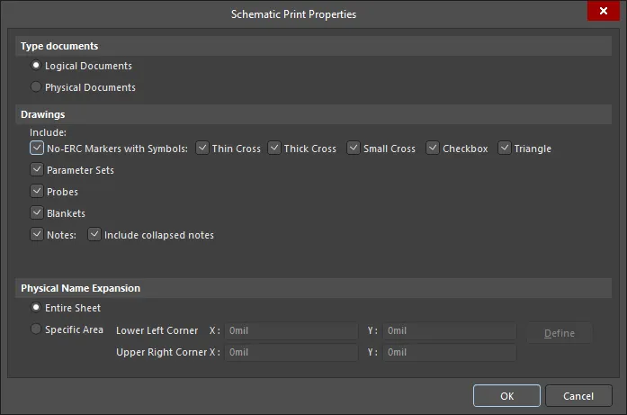
This dialog provides options to configure advanced properties when printing schematic documents.
The dialog is accessed by right-clicking in the Print Preview dialog then choosing Configuration from the context menu.
Options/Controls
Select the type of documents to print. Logical documents are the original schematics. Physical documents are the design as it will be implemented on the board.
Enable or disable the Drawings options to configure the objects' inclusion in the printed outputs.
Use the controls in the Physical Name Expansion region to determine where the physical name expansion occurs. Choose from:
- Entire Sheet - on the entire schematic sheet.
- Specific Area - with this option enabled, the following controls become available:
- Lower Left Corner X/Y - define the X and Y coordinates of the bottom-left corner.
- Upper Right Corner X/Y - define the X and Y coordinates of the top-right corner.
- Define - click to define the required area directly in the design space. A crosshair will appear in the design space; click to define the two diagonally-opposite corners of the area. After defining the two corners, the dialog reappears with the coordinates of your chosen locations in the respective fields.
PCB Printout Properties Dialog
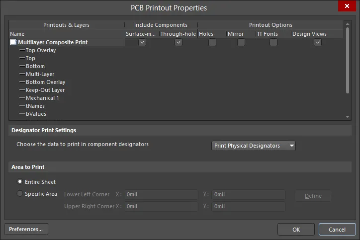
This dialog provides controls to define and manage the printout(s) required for the specific print-based documentation that is to be generated from the board.
The dialog is accessed in the following ways:
- Click Advanced in the Composite Properties dialog.
- Right-click in the Print Preview dialog then choose Configuration from the context menu.
The grid region presents the configured printouts in a grid. The grid is comprised of three columns:
- Printouts & Layers - lists the currently defined printouts and their constituent layers.
- Include Components - this column enables you to control which components are included in an associated printout/printout set; either those on the top, those on the bottom, or components on both sides.
-
Printout Options - this column enables you to control additional options with respect to an associated printout/printout set; whether or not to show holes, mirror layers, and enable font substitution.
The right-click menu of the dialog includes commands to create prints/drawings for the source PCB document as well as
The following list of commands are available from the right-click menu accessed from anywhere within the dialog:
- Create Final - use this command to quickly create a complete, predefined final artwork print-set for the source PCB document.
- Create Composite - use this command to quickly create a predefined multi-layer composite print for the source PCB document.
- Create Power-Plane Set - use this command to quickly create predefined power-plane drawings for the source PCB document.
- Create Mask Set - use this command to quickly create predefined solder/paste mask drawings for the source PCB document.
- Create Drill Drawings - use this command to quickly create a predefined set of drill drawings and guides for the source PCB document.
- Create Assembly Drawings - use this command to quickly create predefined assembly drawings for the source PCB document.
- Create Composite Drill Guide - use this command to quickly create a predefined composite drill drawing for the source PCB document.
-
Insert Printout - use this command to insert a new standard printout for the print-based output currently being configured. The printout will be added immediately above the currently focused printout/printout set.
- Insert Drill Printout Set - use this command to insert a new drill printout set for the print-based output currently being configured. The drill printout set will be added immediately above the currently focused printout/printout set.
- Insert Layer/Insert Layer Class - use this command to insert a new layer or layer class into the focused printout/printout set. The Layer Properties dialog will open in which you can choose from a list of all used layers/classes for the board. The layer will be added immediately above the focused entry within that printout/printout set.
- Move Up - use this command to move the focused entry upward within a printout/printout set, or move the focused printout/printout set upward within the overall print set.
- Move Down - use this command to move the focused entry downward within a printout/printout set, or move the focused printout/printout set downward within the overall print set.
-
Delete - use this command to remove the selected entry(ies) from the associated parent printout/printout set or the selected printout(s)/printout set(s) from the overall print-set currently being configured. You will be prompted to confirm the deletion.
- Properties - use this command to open the appropriate properties dialog.
-
Preferences - use this command to open the PCB Print Preferences dialog in which you can define global options that apply to all print sets.
- Designator Print Setting - use to specify the type of designator information to be included on the printouts.
- Area to Print - use to determine the area of the board to be printed.
- Preferences - use to open the PCB Print Preferences dialog to define printout-related preferences including the coloring for each layer that can be printed, whether any mechanical layers are included in a printout automatically, and font substitution.
Printout Properties Dialog
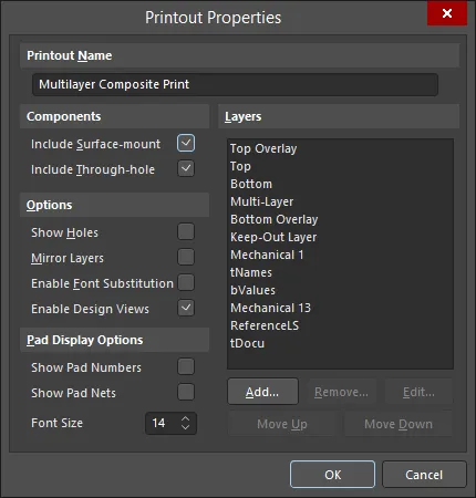
This dialog provides controls to configure the properties of a newly-added or existing printout/printout set.
The dialog is accessed from the PCB Printout Properties dialog in the following ways:
- Double-click on the icon to the left of a printout's/printout set's name.
- Select a printout/printout set, right-click then choose Properties from the context menu.
The key options are described below.
Layers - this region is the 'heart' of printout configuration and provides the necessary controls to add, edit and order the layers that are to make up the printout.
-
Layer List - a list of the layers currently included on the printout (or each printout in a printout set). The layer at the bottom of the list will be drawn first in the printer's memory when the image is rendered. Each layer above is then rendered, in turn, on top. Select a layer then use the Move Up and Move Down buttons to change its position in the render order.
- Add - click to add another layer to the printout (or each printout in a printout set). The Layer Properties dialog will open in which you can choose from a list of all used layers for the board, and with which to configure the properties for the chosen layer as required. The new layer will be added to the bottom of the list.
-
Remove - click to remove the selected layer entity(ies) from the list.
-
Edit - click to edit the currently selected layer entity on the list. The Layer Source Properties dialog will open in which you can configure the properties for the entity as required.
Layer Properties Dialog
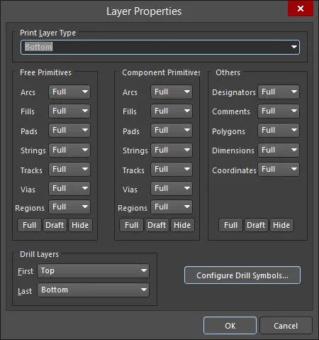
This dialog provides controls to configure the properties of a newly-added or existing layer entity.
- From the PCB Printout Properties dialog:
- Double-click on the entry for an existing layer entity.
- Select an existing layer entity, right-click then choose Properties from the context menu.
- From the Printout Properties dialog:
- Double-click on the required layer in the Layers region.
- Select the required layer in the Layers region then click the Edit button.
The Free Primitives, Component Primitives and Others regions provide controls to determine how primitives on a layer are displayed on the printout. For the listed objects, use the associated drop-down to choose whether to display the object fully (Full), in outline mode only (Draft), or hide the object (Off). Buttons at the bottom of the region can be used to quickly switch the setting for all objects in a single action.
Click the Configure Drill Symbols button to open the Drill Symbols dialog.
PCB Print Preferences Dialog

This dialog provides controls to define global print preferences that are applied to all PCB-related print output (with the exception of PCB 3D Prints).
The dialog is accessed by clicking the Preferences button at the bottom-left of the PCB Printout Properties dialog.
The key options are described below.
Colors & Gray Scales
- Main Grid - this area allows you to control the coloring that is used for each possible layer that can be printed.
-
Retrieve Layer Colors From PCB - click if you want to print using the same colors configured for the PCB design in the PCB Editor.
Advanced Text Print Properties Dialog
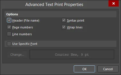
This dialog provides controls to configure more advanced properties when printing text documents.
The dialog is accessed in the following ways:
-
Click Advanced in the Text Print Properties dialog.
-
Right-click in the Print Preview dialog then choose Configuration from the context menu.
PCB 3D Print Settings Dialog
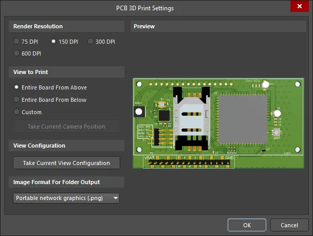
This dialog allows you to define settings when generating a print of the board in 3D.
The dialog is accessed by selecting Configure for the PCB 3D Print output in the Generate Outputs dialog.
Render Resolution
Use this region to specify the quality of the 3D model to be printed in terms of resolution.
View to Print
Use this region to select the view of the board to be printed. Choose from the following options:
- Entire Board From Above - choose to print the 3D view of the board looking directly down from above the board (camera perspective is perpendicular to the board).
- Entire Board From Below - choose to print the 3D view of the board looking directly up from below the board (camera perspective is perpendicular to the board).
- Custom - choose this option then click Take Current Camera Position to print the 3D view of the board as it is currently displayed in the PCB editor.
View Configuration
Click Take Current View Configuration to apply the current design space view configuration settings for surface colors, visibility, opacity, and board thickness.
Image Format for Folder Output
Use the drop-down menu to select the image format for the generated print. Choose from.bmp,.jpg, and.png.
Preview
This region displays a preview of what will be printed. It will dynamically update as changes are made in the View to Print and/or View Configuration regions of the dialog.
Printer Configuration Dialog

The Printer Configuration dialog provides controls to define what is printed and to which printing device it is sent.
The dialog is accessed in the following ways:
- Right-click on a document entry in the Projects panel then choose Print from the context menu.
- Click Print or Printer Setup in the associated Print Properties dialog (accessed using the relevant Page Setup control).
- From the Print Preview dialog by:
- Clicking the Print button at the bottom of the dialog.
- Right-clicking then choosing either the Print command or the Setup Printer command from the context menu.
Report Preview Dialog
The Report Preview dialog can be accessed wherever the software generates a report that offers an intermediate preview rather than a directly generated report. Some examples include:
- Right-click in a region of the PCB panel and select the Report command from the context menu when, for example, browsing loaded nets and components.
- Use the Report button (or Report command on the right-click menu) when browsing design rules in the PCB Rules and Constraints Editor dialog.
- Right-click in a region of the PCB Rules and Violations panel then select the Report command from the context menu.
