
Preparing Autodesk Inventor for CoDesign
Altium CoDesigner is an interface for transferring printed circuit board designs between the ECAD and MCAD design domains. Once the CoDesigner add-in has been added to your MCAD software, CoDesigner can pass design changes back and forth. Design changes are passed through an Altium Workspace, which acts as a bridge between the ECAD and MCAD domains.
► Check the version compatibility between your MCAD software and CoDesigner
Installing and Configuring CoDesigner in Autodesk Inventor
To interface to and from Autodesk® Inventor® you need to install the MCAD CoDesigner for Autodesk Inventor Add-In.
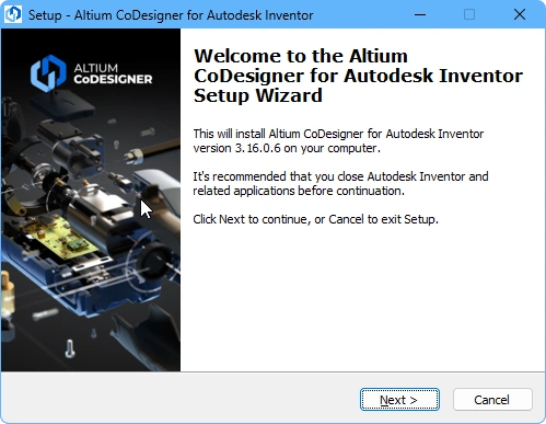 Install and enable the Add-In to access CoDesigner in Autodesk Inventor.
To install the Add-In:
-
Close Autodesk Inventor before installing.
-
Download and install the Autodesk Inventor Add-In (refer to the Download details below).
-
Run the MCAD CoDesigner installer.
-
Launch Autodesk Inventor and confirm that the Add-In is installed and enabled for loading in the Add-In Manager dialog (
 ).
-
Once the Add-In has been enabled the Altium CoDesigner panel can be accessed through the Altium CoDesigner tab on the ribbon, as described below. All collaboration activities are performed through this panel.
Displaying the CoDesigner Panel
In Autodesk Inventor, the Altium CoDesigner panel can be enabled by switching to the Altium CoDesigner tab on the ribbon, and then clicking the panel button, as shown below.
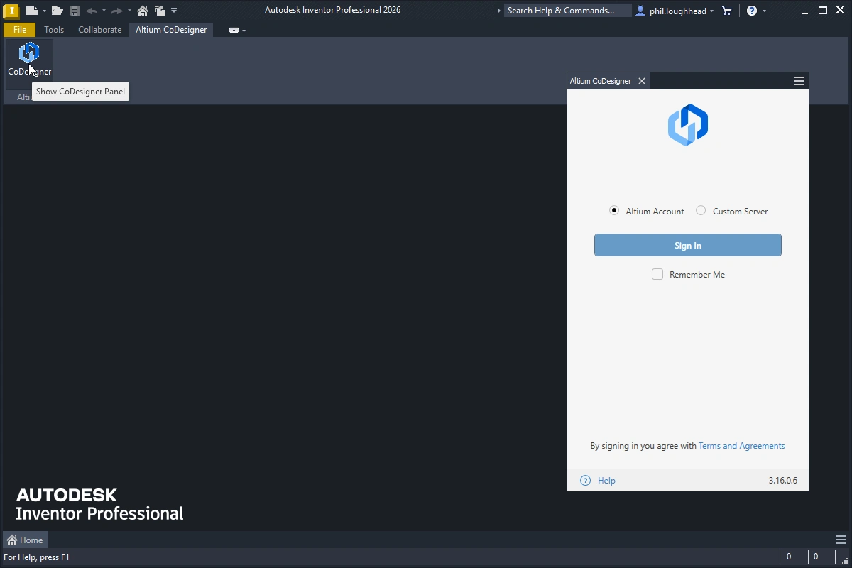 CoDesigner is accessed through an Autodesk Inventor panel.
If the Altium CoDesigner panel does not automatically appear in Autodesk Inventor:
-
Select the Altium CoDesigner tab on the ribbon, as shown above.
-
Click the Show CoDesigner panel button to display the panel.
Connecting to your Workspace from Autodesk Inventor
MCAD CoDesigner in Autodesk Inventor collaborates with your ECAD software (Altium Designer) through an Altium Workspace, which you must sign in to the first time you use it. When you are not signed in, the Altium CoDesigner panel offers two sign-in modes, one for signing into an Altium 365 Workspace – Altium Account, the other for signing in to a Workspace on an On-Prem Enterprise Server – Custom Server.
From version 3.16 and higher Altium MCAD CoDesigner uses Altium's unified login system, the same system used across other Altium solutions, such as Altium Designer. The system is simple to use, once you've selected the type of Altium Workspace that you'll be connecting to, click the Sign In button. A browser window will open, where you complete the sign in process.
Learn more about Logging in to Altium MCAD CoDesigner.
Once you have signed in, you are ready to start collaborating on board designs through Altium MCAD CoDesigner.
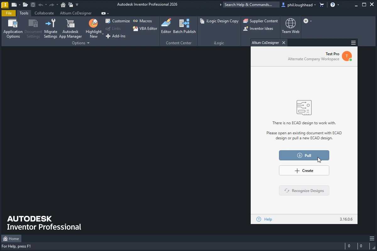 CoDesigner has been installed and is ready to use. Click Pull to pull a board design from ECAD.
Managing MCAD CoDesigner
The top of the Altium CoDesigner panel displays your user name, the Workspace you are currently connected to, and an identity icon. The icon includes a dot that reflects the Workspace connection status.
Click anywhere on the text or icon to display the MCAD CoDesigner menu, as shown below. From here you can: switch to another Workspace (if available), configure your profile, access the collaboration settings, and Sign Out of your Altium Account.
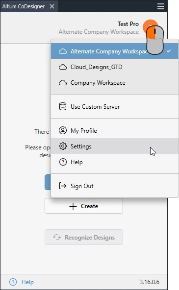 Click anywhere on the text or icon at the top of the panel to display the MCAD CoDesigner menu.
Configuring the Autodesk Inventor Collaboration Settings
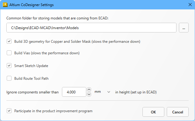
Once you have signed in, CoDesigner settings can be configured in the Altium CoDesigner Settings dialog, opened via the Settings menu entry in the CoDesigner menu, as shown above.
-
Common folder for storing models that are coming from ECAD - All component models created by CoDesigner are stored in this location, regardless of the project they belong to (note that the board part and board assembly are created by CoDesigner in the project folder specified during the initial pull into Autodesk Inventor). If no location is specified, all component models will be created in the project folder and will be unavailable for reuse in other projects.
-
Build 3D geometry for Copper - Top and bottom layer copper layers are always represented as decals on the surfaces of the board part. When this option is enabled, CoDesigner will also create extruded features to represent all copper layers, as well as thruhole pads. Note that enabling this option can create a large amount of data that significantly impacts performance.
-
Build Vias - enable this option to also include the Via barrels. Note that enabling this option can create a large amount of data that significantly impacts performance.
-
Smart Sketch Update - when enabled, during a Pull MCAD CoDesigner only redraws the elements of a sketch that were changed in ECAD, keeping dimensions and constraints related to non-changed elements as they were. Disable this option if it produces undesirable results. Learn more about Smart Sketch Change support.
-
Build Route Tool Path – The Route Tool Path is an outline defined for milling the board out of the panel that it is fabricated on. Disable this option if the path is not required in MCAD. Learn more about the ECAD Route Tool Path.
-
Ignore components smaller than
<Value><Units>in height - Smaller components can be excluded from the synchronization process. Configure this option to exclude components less than<Value><Units>when a Pull is performed. Note that the component height is defined in ECAD as a property of the component (footprint), it is not the height of the 3D model placed on the footprint. Learn more about configuring CoDesigner to ignore smaller components. -
Participate in the product improvement program - enable this option to automatically share technical information with Altium about your use of CoDesigner. Learn more about the product improvement program.
Where to Next?
Now that CoDesigner is installed in your MCAD software and connected to your Workspace, the next step is to configure the relevant Workspace settings.
► Learn more about Configuring your Workspace Settings