
Creating Harness Template Documents
When applied to a wiring diagram or layout drawing, a harness template document defines the size, the graphics (such as the title block), and the list of document-level parameters of this document. You can create your own set of templates to facilitate providing consistent-looking harness design documents created by you or the entire team.
Creating a Workspace Wiring Diagram or Layout Drawing Template
-
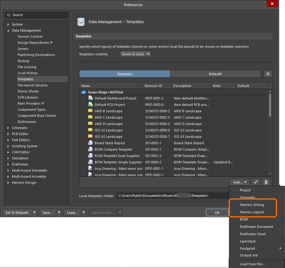
Open the Templates tab of the Data Management – Templates page of the Preferences dialog.
-
Select the Harness Wiring or Harness Layout command from the menu of the
 button or the right-click menu of the template grid.
-
After selecting a command, click OK in the Close Preferences dialog that opens to close the Preferences dialog and open the temporary editor for the template. A planned revision of the new template will be created automatically in a Workspace folder of the Harness Wiring Templates / Harness Layout Templates type.
-
Configure options of the design space using the General tab of the Properties panel when no object is selected in the design space.
-
In the General region of the panel, select the units and configure the grid options.

-
In the Page Options region of the panel, select Standard or Custom in the Formatting and Size region and configure the provided options as required – set sheet size and orientation, enable or disable using the default title block, and set margin and zones.


-
-
Define the set of parameters on the Parameters tab of the Properties panel in its Documents Options mode. These parameters will become document-level parameters of the wiring diagram / layout drawing document to which the template will be applied. Use the controls at the bottom of the panel to add and remove used-defined parameters.

-
Using drawing objects, define the template's look. For example, if you opted not to include a default title block, create a custom title block using these objects.
You can also use text strings to define the static text strings of the template, i.e., the text that will not be changed in the document (e.g.,
Drawn Bytext).
An example custom title block created using line and text objects. -
Use text string objects as special strings to define placeholders for design or system information that will be substituted with parameter values when the template is applied to a document. Define the Text property of a selected text string in the format
=<ParameterName>. When applied to a document, this text string will show the value of the parameter with the same name. This can be a sheet-level parameter (predefined or user-defined) or a project-level parameter.For example, a text string with the
=DrawnBytext will show the value of theDrawn Byparameter (where, for example, your name is entered) when the template is applied to a document.
An example custom title block with special strings added. These special strings will be updated with actual parameter values when the template is applied to a document. -
Save the template to the connected Workspace by selecting the File » Save to Server command from the main menus. The Edit Revision dialog will appear, in which you can define the Name and Description of the template item being created in the Workspace and add release notes as required.
The template can now be applied to a wiring diagram / layout drawing document. When the document is active, open the Properties panel in its Documents Options mode (active when no object is selected in the design space), and in the Page Options region of the General tab, select Template mode for Formatting and Size and then use the Template drop-down to select from available templates.

A wiring diagram template was applied to a wiring diagram document. Note that placeholder special strings have been updated with parameter values.
Saving an Existing Local Wiring Diagram or Layout Drawing Template to the Workspace
-
You can create a new Workspace wiring diagram or layout drawing template using the Load from File command from the menu of the
button or the Add context menu of the template grid on the Templates tab of the Data Management – Templates page of the Preferences dialog. In the Open dialog (a standard Windows open-type dialog) that opens, select the Harness Wiring Diagram Template File (*.WirDot) and Harness Layout Diagram Template File (*.LdrDot) option in the drop-down at the right of the File name field and use the dialog to browse to and open the required file that will be uploaded into the initial revision of the new Workspace template created automatically in a Workspace folder of the Harness Wiring Templates / Harness Layout Templates type.
-
If the required wiring diagram or layout drawing template to be saved to the Workspace resides in the Local Template folder (denoted at the bottom of the Data Management – Templates page of the Preferences dialog) and is listed under the Local entry of the template grid, it can be migrated to a new Harness Wiring Template Item / Harness Layout Template Item by right-clicking on it and selecting the Migrate to Server command. Click the OK button in the Template migration dialog to proceed with the migration process – as stated in this dialog, the original template file will be added to a Zip archive in the local template folder (and hence, it will not be visible under the Local template list).
-
If you need to update a Workspace wiring diagram or layout drawing template and you have an updated template file, you can upload that file to the Workspace template. From the Templates tab of the Data Management – Templates page of the Preferences dialog, right-click on the template entry and choose the Upload command from the context menu. Use the Open dialog (a standard Windows open-type dialog) that opens to browse and open the required file that will be uploaded into the next revision of the Workspace template.
Editing a Workspace Wiring Diagram or Layout Drawing Template
At any stage, you can return to a wiring diagram or layout drawing template in the Workspace and edit it. From the Templates tab of the Data Management – Templates page of the Preferences dialog, right-click on the template entry and choose the Edit command from the context menu. The temporary editor will open, with the template contained in the revision opened for editing. Make changes as required, then save the document into the next revision of the template.
Creating a Local Wiring Diagram or Layout Drawing Template
A local wiring diagram or layout drawing template can also be created. To do this:
-
When a harness design project is the active project, create a new wiring diagram document/layout drawing document by selecting the File » New » Harness Wiring Diagram or File » New » Harness Layout Drawing command, respectively, from the main menus.
-
Use the document to define the template as required and described above.
-
Select the File » Save As command from the main menus. In the Save As dialog that appears, browse to the local templates folder for your installation of Altium Designer (denoted in the Local Templates folder field at the bottom of the Data Management – Templates page of the Preferences dialog;
C:\Users\Public\Documents\Altium\AD<Solution/Version>for the default installation), enter the desired name of the template and select Harness Wiring template (*.WirDot) or Harness Layout template (*.LdrDot) from the Save as type drop-down.


Creating a Manufacturing Drawing Template
A manufacturing drawing template defines a manufacturing drawing document's content and (optionally) its style properties.
To create a new manufacturing drawing document template:
-
When a harness design project is the active project, create a new manufacturing drawing document by selecting the File » New » Draftsman Document command from the main menus.
-
Define the content of the template. The template supports multi-page documents, data for the main document attributes (tables and lists, drawing types, etc.), page settings, and elements that do not depend on the harness design content. A sheet template can be used to define the graphic format of a new or existing drawing document and is also saved as part of a manufacturing drawing document template.

An example of a manufacturing drawing document templateA multi-page manufacturing drawing document might typically contain a wiring diagram view, a layout drawing view, and a BOM table. When saved as a document template, the data from the current harness design is retained to define a drawing content 'shell.'
-
Select the File » Save Copy As or File » Save As command from the main menus. In the Save dialog that appears, browse to the local templates folder for your installation of Altium Designer (defined in the Local Templates folder field at the bottom of the Data Management – Templates page of the Preferences dialog;
C:\Users\Public\Documents\Altium\AD<Solution/Version>for the default installation), enter the desired name of the template and select Altium Draftsman Harness Document Templates (*.HarDot) from the Save as type drop-down.
After clicking Save, an existing drawing document's content and attributes, except those related to data extracted from the harness design, will be saved as a manufacturing drawing document template. If the source drawing document has a specific page style (as might be applied by a sheet template), these graphical elements and attributes will be saved with the new manufacturing drawing document template.
When subsequently used as a template for a new manufacturing drawing document, the project data is loaded into the shell in place of the template data, therefore recreating the document format and its type of content.
