
Validating the Harness Design
At a Glance
- Learn where to configure harness validation checks and how to run validation on your project.
- Understand how to use the Messages panel to review, sort, group, and locate reported violations in the design.
- See the main harness violation types you may encounter in layout drawings and wiring diagrams, along with the article’s recommended resolution guidance.
Altium Designer can check your harness design for logical, electrical, and drafting violations between the design content and project checking settings. There are a number of checks that can be performed on the harness design configured as part of the project options.
Configuring the Verification Options and Running the Validation
Select the Project » Project Options command from the main menus to open the Project Options dialog and select its Error Reporting tab. The Report Mode of each violation can be changed to one of four values by clicking on it and selecting the desired value in the drop-down.
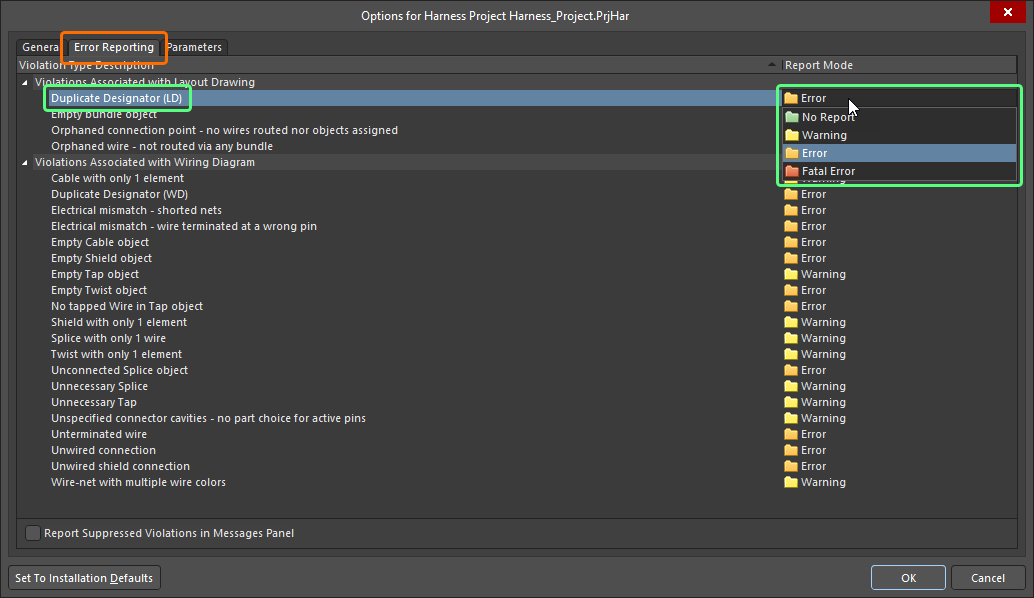
Configure the required violation checks on the Error Reporting tab of the Project Options dialog.
To validate your harness design, right-click the project entry in the Projects panel and select the Validate Harness Project <ProjectName> command from the context menu. To validate a harness project focused in the Projects panel, you can also use the Project » Validate Harness Project <ProjectName> command from the main menus or the  control at the top of the panel.

Validate your harness design using the Validate Harness Project <ProjectName> command.
Interpreting Messages and Locating Violations
Once the project has been validated, the Messages panel will list any check violations that have been detected.
 button at the bottom right of the design space and choosing Messages).
The Messages panel is command central for presenting violations. Things to be aware of include:
-
The Messages panel has two regions – the upper grid region summarizes the violations; the lower region gives details of the currently selected violation.
-
Double-click on a message to cross-probe to that violation. Double-click on a detail to show that specific object.
-
You can click on any of the Messages panel column headings (e.g., Class, Document, Message) to assist in sorting the errors and warnings.
-
Right-click in the Messages panel then use the Group By sub-menu options to group the errors and warnings by specific criteria.
-
Right-click in the Messages panel then use the appropriate Clear command to delete messages or use the Export To Report command to export the messages to a report.
If validation errors and warnings are enabled for display in documents (enabled on the Schematic – Compiler page of the Preferences dialog), an offending object will display a colored squiggle beneath it. Hovering over the object will display a pop-up hint that summarizes the violation.

Harness Design Violation Types
The sections below include detailed information about each violation check available for harness designs.
Violations Associated with Layout Drawing
Duplicate Designator (LD)
This violation occurs when at least two objects in the layout drawing have the same designator associated with them.
Notification
A notification is displayed in the Messages panel in the following format:
Duplicate Designator <Designator>
where Designator is the offending designator.
Recommendation for Resolution
Assign different and unique designators to the duplicates as required. This can be done in the Properties panel by editing each offending designator when the object is selected.
Object designators can also be updated using the Annotate dialog (Tools » Annotate Harness Layout Drawings). Alternatively, reset the duplicate designators first using the Tools » Annotation » Reset Duplicate Harness Layout Drawing Designators command, then use the Tools » Annotation » Annotate Harness Layout Drawings Quietly command to annotate without launching the Annotate dialog.
Refer to the Creating the Layout Drawing page to learn more about annotating layout drawing objects.
Empty bundle object
This violation occurs when no wires or cables are routed through a bundle.
Notification
A notification is displayed in the Messages panel in the following format:
Empty Bundle object <BundleDesignator>
where BundleDesignator is the designator of the offending bundle.
Recommendation for Resolution
Check that the physical arrangement on the layout drawing is defined correctly. Make sure that the offending bundle starts and ends at a connection point and that the objects are assigned to the connection points as required (check the Assigned Objects region of the Properties panel when the connection point is selected).
Refer to the Creating the Layout Drawing page to learn more about defining physical arrangement on a harness layout drawing.
Orphaned connection point - no wires routed nor objects assigned
This violation occurs when no object is assigned to the connection point and no bundles are connected to it.
Notification
A notification is displayed in the Messages panel in the following format:
Orphaned Connection Point <ConnectionPointDesignator>
where ConnectionPointDesignator is the designator of the offending connection point.
Recommendation for Resolution
Make sure that at least one object is assigned to the offending connection point or at least one bundle is connected to the connection point. To assign objects to a connection point, select it and add the required objects using the Assigned Objects region of the Properties panel. Alternatively, if the connection point is not required in the layout drawing, remove it.
Refer to the Creating the Layout Drawing page to learn more about working with connection points.
Orphaned wire - not routed via any bundle
This violation occurs when there is a wire connection imported from the wiring diagram, but the connection is not routed through any bundle.
Notification
A notification is displayed in the Messages panel in the following format:
Orphaned Wire <WireDesignator> - not routed via any bundle
where WireDesignator is the designator of the offending wire.
Recommendation for Resolution
Check that the physical arrangement on the layout drawing is defined correctly. Make sure that each bundle starts and ends at a connection point and that the objects are assigned to the connection points as required (check the Assigned Objects region of the Properties panel when the connection point is selected).
Refer to the Creating the Layout Drawing page to learn more about defining physical arrangement on a harness layout drawing.
Violations Associated with Wiring Diagram
Cable with only 1 element
This violation occurs when a cable object covers only one wire on the wiring diagram.
Notification
A notification is displayed in the Messages panel in the following format:
Cable with only 1 element <CableDesignator>
where CableDesignator is the designator of the offending cable.
Recommendation for Resolution
Move or edit the offending cable object so it covers more than one wire, or remove the object if the cable is not required.
Refer to the Defining the Wiring Diagram page to learn more about working with cables.
Duplicate Designator (WD)
This violation occurs when at least two objects in the wiring diagram have the same designator.
Notification
A notification is displayed in the Messages panel in the following format:
Duplicate Designator <Designator>
where Designator is the offending designator.
Recommendation for Resolution
Assign different and unique designators to the duplicates as required. This can be done in the Properties panel by editing each offending designator when the object is selected.
Object designators can also be updated using the Annotate dialog (Tools » Annotate Harness Wiring Diagrams). Alternatively, reset the duplicate designators first using the Tools » Annotation » Reset Duplicate Harness Wiring Diagram Designators command, then use the Tools » Annotation » Annotate Harness Wiring Diagrams Quietly command to annotate without launching the Annotate dialog.
Refer to the Defining the Wiring Diagram page to learn more about annotating wiring diagram objects.
Electrical mismatch - shorted nets
This violation occurs when wires representing different logical connections imported from the multi-board design are connected to each other.
Notification
A notification is displayed in the Messages panel in the following format:
Electrical mismatch - shorted nets
Recommendation for Resolution
Make sure that there are no connections between wires representing different logical connections imported from the multi-board design. Component pins related to different logical connections might be connected, or wires representing different logical connections might be connected through splices.
Refer to the Defining the Wiring Diagram page to learn more about creating connectivity in the harness wiring diagram.
Electrical mismatch - wire terminated at wrong pin
This violation occurs when a wire connects component pins related to different logical connections imported from the multi-board design.
Notification
A notification is displayed in the Messages panel in the following format:
Electrical mismatch - wire terminated at wrong pin
Recommendation for Resolution
Make sure that there are no wires between component pins related to different logical connections imported from the multi-board design.
Refer to the Defining the Wiring Diagram page to learn more about creating connectivity in the harness wiring diagram.
Empty Cable object
This violation occurs when a cable object covers no wire on the wiring diagram.
Notification
A notification is displayed in the Messages panel in the following format:
Empty Cable object <CableDesignator>
where CableDesignator is the designator of the offending cable.
Recommendation for Resolution
Move or edit the offending cable object so it covers wires, or remove the object if the cable is not required.
Refer to the Defining the Wiring Diagram page to learn more about working with cables.
Empty Shield object
This violation occurs when a shield or shield with connection object covers no wire on the wiring diagram.
Notification
A notification is displayed in the Messages panel in the following format:
Empty Shield object
Recommendation for Resolution
Move or edit the offending shield object so it covers wires, or remove the object if the shield is not required.
Refer to the Defining the Wiring Diagram page to learn more about working with shields.
Empty Tap object
This violation occurs when no wire is connected to a tap object, and no wire is placed through the tap.
Notification
A notification is displayed in the Messages panel in the following format:
Empty Tap object <TapDesignator>
where TapDesignator is the designator of the offending tap.
Recommendation for Resolution
Connect a wire to the offending tap and place a wire so it goes through the tap, or remove the object if the tap is not required.
Refer to the Defining the Wiring Diagram page to learn more about working with taps.
Empty Twist object
This violation occurs when a twist object covers no wire on the wiring diagram.
Notification
A notification is displayed in the Messages panel in the following format:
Empty Twist object
Recommendation for Resolution
Move or edit the offending twist object so it covers wires, or remove the object if the twist is not required.
Refer to the Defining the Wiring Diagram page to learn more about working with twists.
No tapped Wire in Tap object
This violation occurs when a wire is connected to a tap object, but no wire is placed through the tap.
Notification
A notification is displayed in the Messages panel in the following format:
No tapped Wire in Tap object <TapDesignator>
where TapDesignator is the designator of the offending tap.
Recommendation for Resolution
Place a wire so it goes through the offending tap.
Refer to the Defining the Wiring Diagram page to learn more about working with taps.
Shield with only 1 element
This violation occurs when a shield object covers only one wire on the wiring diagram.
Notification
A notification is displayed in the Messages panel in the following format:
Shield with only 1 element
Recommendation for Resolution
Move or edit the offending shield object so it covers more than one wire, or remove the object if the shield is not required.
Refer to the Defining the Wiring Diagram page to learn more about working with shields.
Splice with only 1 wire
This violation occurs when only one wire is connected to a splice object.
Notification
A notification is displayed in the Messages panel in the following format:
Splice with only 1 wire <SpliceDesignator>
where SpliceDesignator is the designator of the offending splice.
Recommendation for Resolution
Connect more wires to the splice so it represents a case when a physical wire is connected to another physical wire.
Refer to the Defining the Wiring Diagram page to learn more about working with splices.
Twist with only 1 element
This violation occurs when a twist object covers only one wire on the wiring diagram.
Notification
A notification is displayed in the Messages panel in the following format:
Twist with only 1 element
Recommendation for Resolution
Move or edit the offending twist object so it covers more than one wire, or remove the object if the twist is not required.
Refer to the Defining the Wiring Diagram page to learn more about working with twists.
Unconnected Splice object
This violation occurs when no wire is connected to a splice object.
Notification
A notification is displayed in the Messages panel in the following format:
Unconnected Splice object <SpliceDesignator>
where SpliceDesignator is the designator of the offending splice.
Recommendation for Resolution
Connect wires to the splice so it represents a case when a physical wire is connected to another physical wire.
Refer to the Defining the Wiring Diagram page to learn more about working with splices.
Unnecessary Splice
This violation occurs when only two wires are connected to a splice object.
Notification
A notification is displayed in the Messages panel in the following format:
Unnecessary Splice <SpliceDesignator>
where SpliceDesignator is the designator of the offending splice.
Recommendation for Resolution
Connect more wires to the splice so it represents a case when a physical wire is connected to another physical wire.
Refer to the Defining the Wiring Diagram page to learn more about working with splices.
Unnecessary Tap
This violation occurs when a wire is placed through a tap object, but no wire is connected to the tap.
Notification
A notification is displayed in the Messages panel in the following format:
Unnecessary Tap object <TapDesignator>
where TapDesignator is the designator of the offending tap.
Recommendation for Resolution
Connect a wire to the offending tap.
Refer to the Defining the Wiring Diagram page to learn more about working with taps.
Unspecified connector cavities - no part choice for active pins
This violation occurs when a component has one or more pins with no socket cavities assigned, and wires are connected to these pins.
Notification
A notification is displayed in the Messages panel in the following format:
Unspecified connector cavities - no part choice for active pins in <ComponentDesignator>
where ComponentDesignator is the designator of the offending component.
Recommendation for Resolution
Make sure that all pins of the offending component to which wires are connected have assigned cavities. Select the component and navigate to the Cavities tab of the Properties panel to configure cavities for this component.
Refer to the Defining the Wiring Diagram page to learn more about assigning socket cavities.
Unterminated wire
This violation occurs when an unterminated wire is present in a wiring diagram.
Notification
A notification is displayed in the Messages panel in the following format:
Unterminated wire <WireDesignator>
where WireDesignator is the designator of the offending wire.
Recommendation for Resolution
Make sure that the offending wire is terminated on a component pin or, if it should stay unconnected according to the design intent, a 'no connect' object is placed at the unterminated end of the wire.
Refer to the Defining the Wiring Diagram page to learn more about working with unconnected wires.
Unwired connection
This violation occurs when a logical connection imported from the multi-board design is not completed with wires in the wiring diagram.
Notification
A notification is displayed in the Messages panel in the following format:
Unwired connection <LogicalConnectionDesignator>
where LogicalConnectionDesignator is the designator of the offending logical connection.
Recommendation for Resolution
Make sure that the offending connection is completed, i.e., all component pins of the same logical connection are connected with wires.
Refer to the Defining the Wiring Diagram page to learn more about creating connectivity in the harness wiring diagram.
Unwired shield connection
This violation occurs when a shield with connection object is placed in the wiring diagram, but no wire is connected to the object.
Notification
A notification is displayed in the Messages panel in the following format:
Unwired shield connection
Recommendation for Resolution
Make sure that a wire is connected to the offending shield with connection object, or use the shield object instead if the shield connection is not needed.
Refer to the Defining the Wiring Diagram page to learn more about working with shields with connection.
Wire-net with multiple wire colors
This violation occurs when wires of different colors are connected to the same splice object or when wires of different colors are placed through and connected to a tap object.
Notification
A notification is displayed in the Messages panel in the following format:
Wire-net with multiple colors at splice <SpliceDesignator>
where SpliceDesignator is the designator of the offending splice.
Recommendation for Resolution
Make sure that wires of the same color are connected to the offending splice or wires of the same color are placed through and connected to the offending tap.
Refer to the Defining the Wiring Diagram page to learn more about working with splices and taps.