
Draftsman Placement & Editing Techniques
A variety of objects are available for use in creating a PCB drawing. The Draftsman editor's design space can contain a large number of design objects that make up the drawing. During the course of the drawing creation process, the placement and properties of these objects need to change as you work to achieve the required look of your drawing.
Object Placement and Editing Commonality
In Altium Designer's Draftsman, the process of placing an object is roughly the same regardless of the object being placed. At its simplest level, the process is as follows:
-
Select the object to be placed from one of the following locations:
-
The main Place menu.
-
The Active Bar located at the top of the design space.
-
The Place submenu of the design space right-click menu.
-
-
When an object is selected for placement, drawing data is retrieved from the source PCB file (where applicable), and the cursor will change to a crosshair, indicating that you are in editing mode, and if relevant, the object will appear "floating" under the cursor. Position the cursor then click or press
Enterto place the object. For some objects, such as dimensions, you must continue the position-and-click procedure to define all relevant locations of the object. -
After placing a non-view type object, you will remain in placement mode (indicated by the crosshair cursor), allowing you to immediately place another object of the same type. To end placement mode, right-click or press the
Esckey. In some cases, such as placing a region object, you may need to do this twice; once to finish placing the object and once to exit placement mode. When you exit placement mode, the cursor will return to its default shape.
Editing Prior to Placement
The default properties for an object can be changed at any time on the Draftsman – Defaults page of the Preferences dialog. Most properties of an object, or those that can logically be pre-defined, are available as editable default settings. These properties will be applied when placing subsequent objects. Select an object in the Primitive List to reveal its options on the right.

Use the Primitive List column to access properties for objects and edit default values as required.
Editing After Placement
Once an object has been placed, there are a number of ways in which it can be edited. These are described below.
The Associated Properties Panel
This method of editing uses the associated Properties panel mode and dialog to modify the properties of a placed object.

The panel automatically changes its content to match the selected object.
To open the Properties panel and access the properties of a placed object:
-
After selecting the object, select the Properties panel from the
 button at the bottom right of the design space or select View » Panels » Properties from the main menus.
-
Double-click the object in the design space.
-
Right-click the object then select Item Properties from the context menu.
If the Properties panel is already active, click on the object to access its properties in the panel. The panel will automatically populate its content to match the property settings for the currently selected object in the design space.
Graphical Editing
This method of editing allows you to select a placed object directly in the design space and change its location and, where supported, its size and shape. The selected object is denoted using one or more of the following techniques:
-
One or more editing handles located at corners and/or end-points.
-
A blue dashed selection bounding box.
-
The object changing color to the blue selection color.
Once selected, you can graphically:
-
Move an object – click and hold anywhere on an object to drag the object to reposition it. If the object supports rotation, press
Spacebarto rotate the object counterclockwise orShift+Spacebarfor clockwise rotation with 90-degree increments. -
Resize an object – if supported, click and drag an editing handle/node to resize the object. Objects that support graphical resizing include view-type objects, annotations, and graphical tools. A layer stack legend and table-type objects do not support graphical resizing.

An example editing handle for a selected board assembly view. Drag the handle to change the view's scale.
Movement and Rotation Commands
Objects can also be moved and rotated using the command of the Move pop-up menu accessed by pressing the M shortcut key.
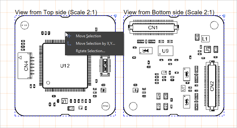
Select the object(s) to move, open the Move pop-up menu, then choose the required command.
| Move Selection | After launching the command, click in the design space then move the cursor with the selection attached and click again once the object(s) are in the desired location. |
| Move Selection By XY | After launching the command, The Get X / Y Offsets dialog opens (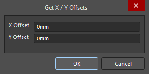 ). Use the dialog's X Offset and Y Offset fields to specify the distance by which the selection(s) should be moved along the horizontal (X) axis and vertical (Y) axis, respectively. Positive and negative values can be specified depending on the direction of movement required. ). Use the dialog's X Offset and Y Offset fields to specify the distance by which the selection(s) should be moved along the horizontal (X) axis and vertical (Y) axis, respectively. Positive and negative values can be specified depending on the direction of movement required. |
| Rotate Selection | After launching the command, the Rotation Angle (Degrees) dialog will open (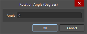 ). Enter the required Angle of rotation from 0.001° to 360.00° (resolution 0.001°). Enter a positive value for counterclockwise rotation or a negative value for clockwise rotation. Click OK to close the dialog then position the cursor and click to define the reference point for rotation. The selected objects will be rotated about the reference point by the entered angle. ). Enter the required Angle of rotation from 0.001° to 360.00° (resolution 0.001°). Enter a positive value for counterclockwise rotation or a negative value for clockwise rotation. Click OK to close the dialog then position the cursor and click to define the reference point for rotation. The selected objects will be rotated about the reference point by the entered angle. |
Using Copy and Paste
In Draftsman, you can cut, copy and paste objects within or between Draftsman documents using the commands of the Edit main menu or standard shortcuts.
Editing Multiple Objects
The Properties panel supports multiple object editing. Note that while it is not possible to make changes to different object types at the same time through the Properties panel, you can make simultaneous changes to multiple selected objects of the same type. Use standard Shift+Click to multi-select – the panel will present the values for the last object added to the selection.
Format Painter
The Format Painter feature offers a simple and fast way to transfer an existing text style to other Draftsman text elements.
As demonstrated in the video below, select an existing text element that has the style properties (as defined in the Properties panel) that you would like to propagate, and then choose the Format Painter command from the Edit main menu or the design space right-click menu. This action effectively captures the style properties of the currently selected text.
Use the cursor, which changes to the Format Painter tool icon (![]() ), to locate and select other text elements that will adopt the style properties. Compatible text objects include editable text elements such as view titles, text objects and note items.
), to locate and select other text elements that will adopt the style properties. Compatible text objects include editable text elements such as view titles, text objects and note items.
Text Search
The Draftsman editor allows you to quickly find specific text (or partial text) in accordance with defined search options. Choose the Edit » Find Text command from the main menus or use the Ctrl+F keyboard shortcut to access the Find Text dialog.

The Find text dialog
Use this dialog to specify the existing text to find, along with scoping and additional options.
Text To find |
|
| Text To Find | Use this field to enter the text string for which you want to search. Either enter the full word or search for a partial string. The latter requires the Whole Words Only option to be disabled. The string can contain the wildcard characters |
Scope |
|
| Sheet Scope | Use this field to determine the scope of the text search in terms of the draftsman documents involved. Choose from the following options:
|
| Selection | Use this field to further constrain the scope of the search based on the current selection status of objects. Choose from the following options:
|
| Identifiers | Use this field to further constrain the scope of the search based on the type of text-based object. Choose from the following options:
|
Options |
|
| Case sensistive | Enable this option to perform a case-sensitive search, meaning the target text must match the case of the search text entered into the Text To Find field. |
| Whole Words Only | Enable this option to restrict the search to whole words only. This means the search text must exist fully as is and not be part of a larger text string. For example, if this option is enabled when looking for cat, the software will not consider the first three letters of category – a valid search match. Disable this option to freely search for partial strings. |
Where a search yields multiple matches, the Find text - Jump dialog opens.

The Find text - Jump dialog
Use the dialog's ![]() and
and ![]() buttons to browse to the previous matching and next text item, respectively. As you step back and forth through the matching occurrences of found text, the upper region of the dialog will reflect the original search text and the current item being viewed in the design space in terms of the type of object and its matching text.
buttons to browse to the previous matching and next text item, respectively. As you step back and forth through the matching occurrences of found text, the upper region of the dialog will reflect the original search text and the current item being viewed in the design space in terms of the type of object and its matching text.
You can also find the next occurrence of the last text search that was specified using the Find text dialog in the document by selecting the Edit » Find Next command from the main menus (shortcut: F3).
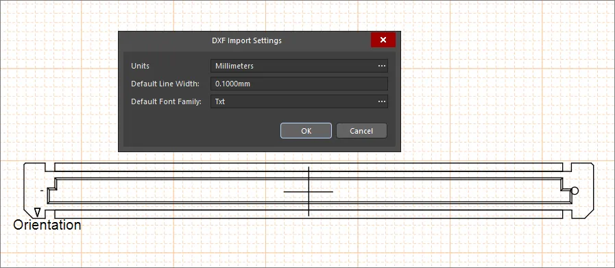
DXF Import
Draftsman provides further graphical options through the import of standard DXF files, which are loaded into the drawing space from the File » Import from DXF menu command. Use the standard Windows Open dialog to select a DXF (*.dxf) file then configure the import options from the DXF Import Settings dialog that opens.
Importing DXF File Versions R12 and Later
You can import DXF files with version R12 and later into manufacturing drawing documents (*.PCBDwf, *.HarDwf, *.MbDwf).
Importing DXF Files with Splines
DXF files including splines can be imported into a manufacturing drawing document (*.PCBDwf, *.HarDwf, *.MbDwf).