Once the wiring diagram and layout drawing are complete, read-only copies of their contents can be placed into the manufacturing drawing document (*.HarDwf) and annotated as required. A manufacturing drawing for a harness design is being created in the Draftsman editor.
Add a manufacturing drawing to the harness project from the Projects panel by right-clicking on the project entry and then selecting Add New to Project » Draftsman Document from the context menu (or use the File » New » Draftsman Document command from the main menus). In the New Document dialog that opens, select an available manufacturing drawing template as required and ensure that a correct Project and harness layout drawing Document is selected.
Options of a manufacturing drawing document can be configured in the Properties panel when no object is selected in the document's design space. Refer to the Setting Up a Draftsman Document page to learn more.
The tabs of the Properties panel when no object is selected in the harness manufacturing drawing document
Once the manufacturing drawing document has been created, any changes made in the wiring diagram or layout drawing can be imported into the manufacturing drawing using the Tools » Import Changes From <LayoutDrawing.LdrDoc> command from the main menus or the right-click menu of the design space. Note that despite the description in the menu command, this will import changes from both the wiring diagram and the layout drawing.
Default properties of manufacturing drawing objects can be configured on the Draftsman – Defaults page of the Preferences dialog. These properties will be applied when placing subsequent objects.
The Bookmarks panel offers a convenient way to navigate and manage a multi-sheet manufacturing drawing. The panel presents an expandable tree view of the complete document structure and includes all document sheets and the primary view objects within those sheets.
Using the Units and Dual_Units options in the Properties panel when no object is selected in the design space, you can select the document's default units of measurements for dimension values and length values shown in tables. If required, units specified at the document level can be overridden in properties of specific objects. Supported units are Millimeters, Mils, Inches, Centimeters, Meters, and Feet.
Layout drawing document parameters are imported into the associated harness manufacturing drawing document. These parameters are listed on the Parameters tab of the Properties panel for the document (vsibility of layout parameters in the list can be toggled using the checkbox next to the icon in the panel) and can be used in special strings. Calculated parameter values such as =ItemRevision and =ItemRevisionLevel1 are also included and interpreted in release-generated outputs.
Working with Views
In a manufacturing drawing document, you can place read-only views of the harness wiring diagram and harness layout drawing included in this project.
Wiring Diagram View
A wiring diagram view (Place » Wiring Diagram View) is an automated graphic composite of the active harness design project's wiring diagram.
An example of a wiring diagram view
Properties of a placed wiring diagram view can be configured in the Properties panel when the view is selected in the design space.
The Properties panel when a wiring diagram view is selected
If your harness project includes multiple wiring diagram documents (learn more), you can choose the wiring diagram document from which a placed wiring diagram view should be generated and updated. When the wiring diagram view is selected, use the Document drop-down in the Properties region of the Properties panel to choose the wiring diagram document for this view ().
When Auto Size is enabled, the wiring diagram view automatically adjusts its size to remove empty space at the borders.
Select the Justification by clicking on the arrow that corresponds with the desired justification or the circle to center. The chosen option for Justification defines the point relative to which the position of the view is changed if its size is updated.
Layout Drawing View
A layout drawing view (Place » Layout Drawing View) is an automated graphic composite of the active harness design project's layout drawing.
An example of a layout drawing view
Properties of a placed layout drawing view can be configured in the Properties panel when the view is selected in the design space.
The Properties panel when a layout drawing view is selected
When Auto Size is enabled, the layout drawing view automatically adjusts its size to remove empty space at the borders.
Select the Justification by clicking on the arrow that corresponds with the desired justification or the circle to center. The chosen option for Justification defines the point relative to which the position of the view is changed if its size is updated.
Additional Views
Additional views can be used to complete your manufacturing drawing: harness detail view and component view.
A harness detail view allows a defined area of an existing drawing that is a floating, magnified view of its detail. Circle and rectangle area options are available for a harness detail view. To place the desired view, select an option (Circle area detail view or Rectangle area detail view) from the Place » Additional Views » Harness Detail View main menu.
An example of a circle area harness detail view applied to a wiring diagram view
An example of a rectangle area harness detail view applied to a wiring diagram view
The component view (Place » Additional Views » Component View) is a drawing view of a single component from the current harness design.
An example of a component view
Drawing Annotation and Dimensioning
A range of additional annotation, dimensioning, and drawing tools are provided to add important information to a manufacturing drawing. These include automated note and highlighting systems, as well as tools to indicate the lengths, sizes, and angles of the object outlines, or the distance between nominated objects.
An example of an annotated layout drawing view
A callout associated with a connector or a connection point and set to display the BOM Item displays BOM item position numbers for the connector/connection point itself and its associated parts. A callout added to the physical view of a component on a layout drawing view will also display BOM item position numbers for all cavities assigned to this component.
When a linear dimension is placed between connection points on a layout drawing view, the Value field (the length of the dimension) is automatically filled with the corresponding harness bundle length.
A manufacturing drawing document allows a bill of materials (BOM), wiring list, connection table, and a generic table to be placed on the drawing. The tabular data is directly derived from the project documents and provides a simple, visual way to convey crucial information for the harness manufacturing processes.
In properties of bill of materials, wiring list, and connection tables, you can specify Length Units and length Value Precision (overriding those specified at the document level). The selected options will be applied to the length values shown in the corresponding table.
For harness wiring components, the Length column in a bill of materials table presents the total length for wires/cables of the same BOM item rather than their individual lengths.
Wire, cable, and harness coverings are length-based objects and the value is displayed in the Length field. The Quantity field for those objects is As Required.
When any table object is copied from the manufacturing drawing document, its content can be pasted into a Microsoft Excel spreadsheet.
A wiring list (Place » Wiring List) is an automatically generated table object that displays the start and end points and parameter values for each wire in the harness.
An example of a wiring list
Properties of a placed wiring list (such as visual attributes and data content) can be configured in the Properties panel when the wiring list is selected in the design space.
The tabs of the Properties panel when a wiring list is selected
Designators of shield with connection objects are displayed in the wiring list when a wire is connected to the object.
If a wire has the No value for its Include Cut parameter, this wire will not be presented in the wiring list.
Wire parameters (and their values) specified in the wiring diagram are reflected in the wiring list. An additional column is added to the wiring list for each wire parameter. These additional columns are hidden by default. Use the visibility controls on the Columns tab of the Properties panel when the wiring list is selected to show these columns in the design space (and hide the default columns if needed).
Cells of the Color column are split to show the secondary and tertiary colors assigned to the wire.
The ColorName column includes the names of the main, secondary, and tertiary colors.
Additional columns for secondary, tertiary, and border colors can be made visible.
For wires in a cable, the Length column in a wiring list displays the individual length of each wire.
For the bulkhead connector (the connector with the largest number of cavities), automatic grouping is applied to the wiring list, ensuring that all of its cavities are correctly grouped in the From column.
Use the and buttons to move a visible column whose entry is selected in the Columns tab to the left or right by one count in the wiring list.
Click a cell in the Order column to cycle between table column data sort order options (off, ascending, and descending). Sorting can be applied to multiple columns on a priority basis by holding Ctrl and clicking cells in the Order column.
The connector with the most wires (and all of its cavities) are automatically grouped in the From column ().
Splitting a Wiring List
The wiring list of an advanced harness design may have a large number of entries, which can be difficult to fit into a drawing document as a single table. Rather than resorting to font and table scaling, multiple custom table entries, or an external document, you can 'split' a wiring list table so that the wiring list will be presented over a number of 'pages.'
In the Properties panel for a placed wiring list, enable the Limit Page Height option in the Pages region to restrict the height of the table to the nominated height entry (Max Page Height) and, therefore, the number of lines shown in the table.
The editor detects that the entire wiring list is not shown, as indicated by the panel's Page entry (for example, Page 1 from 2), and the associated drop-down menu allows you to nominate which page is shown. To add further pages of the wiring list, place another wiring list and specify the next Page in the Pages region of the Properties panel.
Since each page of the wiring list is placed by adding another wiring list table and then configuring it accordingly, the individual wiring list pages can be placed on any sheet in the manufacturing drawing document.
Note that the Max Page Height property specifies the height of the first page in the wiring list table. When the second page is selected (Page 2), the Max Page Height property defines the height of the first excluded page (Page 1). Page 2, therefore, shows the remaining wiring list entries. Start by making the Max Page Height property identical for each page.
Connection Table
A connection table (Place » Connection Table) is an automatically generated table object that shows the wires connected to every connection point (connector pin, splice, etc.) in the harness.
An example of a connection table (for all components)
Properties of a placed connection table (such as visual attributes and data content) can be configured in the Properties panel when the connection table is selected in the design space.
The tabs of the Properties panel when a connection table is selected
You can use the Component option to show the data of all project components in the table or the data of a specific component or splice.
If a wire has the No value for its Include Cut parameter, this wire will not be presented in the connection table.
Wire parameters (and their values) specified in the wiring diagram are reflected in the connection table. An additional column is added to the connection table for each wire parameter. These additional columns are hidden by default. Use the visibility controls on the Columns tab of the Properties panel when the connection table is selected to show these columns in the design space (and hide the default columns if needed).
Cells of the Color column are split to show the secondary and tertiary colors assigned to the wire.
The ColorName column includes the names of the main, secondary, and tertiary colors.
Additional columns for secondary, tertiary, and border colors can be made visible.
For wires in a cable, the Length column in a connection table displays the individual length of each wire.
Use the and buttons to move a visible column whose entry is selected in the Columns tab to the left or right by one count in the connection table.
Click a cell in the Order column to cycle between table column data sort order options (off, ascending, and descending). Sorting can be applied to multiple columns on a priority basis by holding Ctrl and clicking cells in the Order column.
Use the Display drop-down in the Properties panel to configure the data that is displayed in the table:
Wires Only – show only pins that have wires connected to them.
Wires & Parts – show pins that have wires connected to them and any cavity parts added, such as a plug in case of a sealed connector with no wire.
All Cavities – show all pins of all components, irrespective of connected wires and added cavities (for example, if there is a 10-pin component, all 10 pins will be shown in the table).
No Connect – show only 'no connect' objects.
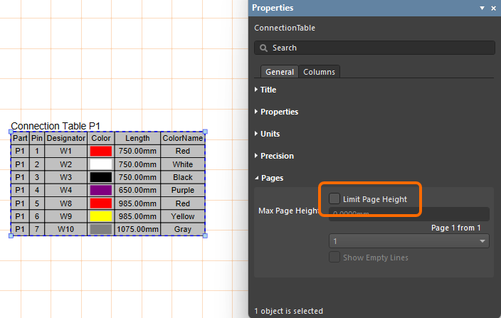
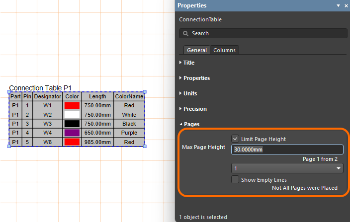
Splitting a Connection Table
The connection table of an advanced harness design may have a large number of entries, which can be difficult to fit into a drawing document as a single table. Rather than resorting to font and table scaling, multiple custom table entries, or an external document, you have the ability to 'split' a connection table in a Harness Draftsman document (*.HarDwf) so that the connection table will be presented over a number of 'pages.' In the Properties panel for a placed connection table, enable the Limit Page Height option in the Pages region to use the new feature. This will restrict the height of the connection table to the nominated height entry (Max Page Height) and, therefore, the number of lines shown in the table.
The editor detects that the entire connection table is not shown, as indicated by the panel's Page entry (for example, 1 from 2), and the associated drop-down menu allows you to nominate which page is shown. To add further pages of the connection table, place another connection table (Place » Connection Table) and specify the next Page in the Pages region of the Properties panel.
If you don’t see a documented feature in your actual software, contact Altium Sales to find out more.
Legacy Documentation
Altium Designer documentation is no longer versioned. If you need to access documentation for older versions of Altium Designer, visit the Legacy Documentation section of the Other Installers page.


 ).
).


 )
) ).
).


")


 )
)