
Controlling the 3D View

Altium Essentials: PCB Introduction
This content is part of the official Altium Professional Training Program. For full courses, materials and certification, visit Altium Training.
The PCB editor is a true, 3-dimensional design space, and you can easily toggle between the 2-dimensional and 3-dimensional display modes. This page describes the PCB editor's features to control the presentation of the board in 3D Layout mode.
To switch to the 3-dimensional display mode: select the View » 3D Layout Mode command from the main menus; use the 3 shortcut; or switch the 3D option in the General Settings region of the View Options tab of the View Configuration panel to the On state. Press the 2 shortcut to switch back to the 2-dimensional display mode.
Navigating a PCB in 3D
In the PCB editor 3D Layout Mode, you can fluidly zoom the view, rotate it and even travel inside the board using various keyboard and mouse combinations. The video below demonstrates these view control techniques.
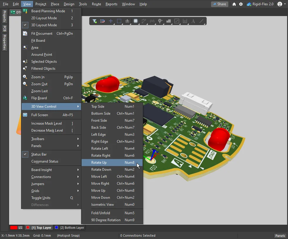
Use the keyboard keys in combination with the right mouse button to orient the 3D view.
Use the following keyboard and mouse combinations to:
 ).
).Rotate
| Display directional sphere | Hold Shift key down When you hold the Shift key down, a directional sphere appears at the current cursor position (as shown in the animation above). Rotational movement of the model is made about the center of the sphere, position the cursor to define the pivot point before pressing Shift. Then use the following controls to rotate the board: |
| Shift + Right-drag mouse | Press and hold Shift to display the sphere, move the mouse around to highlight and select the required control on the sphere, then right-click and perform the Shift + Right-drag mouse action:
|
| Numeric keypad | Press the following numeric keypad key to:
|
 ).
).Re-Orient the View
| Main keyboard |
|
| Numeric keypad |
|
 ).
).Controlling the View as you Switch Between 2D and 3D View Modes
When you press the 2 and 3 shortcuts to switch between 2D and 3D view modes, the default behavior is for each view to retain its last-used view state. That means, if you had the entire board shown in 2D mode, then switched to 3D mode and zoomed in, when you switch back to 2D mode, the entire board will be shown again. This behavior can be overridden if required, by holding the Ctrl+Alt shortcuts as you press 2 or 3.
|
The entire board is shown in 2D If you switch to 3D and then zoom in, when you press 2 to switch back to 2D, the last 2D state (entire board) is shown. Instead, hold Ctrl+Alt as you press 2, to switch to show the board in 2D using the last-used 3D view state. |


3D View Configuration Settings
Both the 2D and 3D view modes are configured in the View Configuration panel. To display the panel: press the L shortcut; use the Panels button at the bottom right of the software; or select the View » Panels » View Configuration menu item.
When you switch to 3D Layout mode, additional options to control the presentation of the board in 3D become available on the View Options tab of the View Configuration panel.
 The View Options tab of the View Configuration panel includes 3D-specific controls.
General Settings
3D Settings
| Board thickness (Scale) | Controls the vertical scale of the 3D view to make it easier to differentiate the layers, for example, when reviewing the layer-to-layer connections of an internal blind via. The transparency of each 3D layer is set below; you can slide to see through the objects on a specific layer. Drag the thickness slider to set the vertical scaling between 1 and 100 times the actual board thickness. |
| Colors – Realistic / By Layer |
The default presentation is to render the 3D board using Realistic colors based on the Configuration currently selected in the General Settings section of this panel. Click the By Layer button to display the 3D view using the current 2D layer color assignments. |
| Grid |
|
| Component transparency | The transparency of 3D components is configured in the 3D Models mode of the PCB panel. Select one or more components to adjust their transparency ( ). ). |
Section View of the 3D Board
A section view allows you to virtually slice the board at a selected location, showing a cut-away view of the board and components. Use this to examine smaller components placed under a larger component or mechanical part, or to examine the structural path of blind and buried vias through the layers of the board. A section view is achieved by defining planes where a section of the PCB is sliced or cut away, along one, two or three of the board axes.
The Section View functionality is available in the PCB editor's 3D layout mode. To enable the section view: select the View » Toggle Section View command; click the ![]() button on the Active Bar; or use the buttons of the Section View option on the Section View tab of the View Configuration panel to toggle the display between Edit, On and Off.
button on the Active Bar; or use the buttons of the Section View option on the Section View tab of the View Configuration panel to toggle the display between Edit, On and Off.
|
Edit mode of the Section View applied to a PCB. On mode of the Section View applied to a PCB. Off mode of the Section View applied to a PCB. |


Section View Controls
| Section View Origin | When the section view is enabled, the current origin is indicated by the triple-arrow gizmo (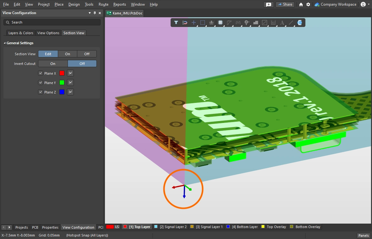 ). PCB objects that exist beyond the origin (in the positive section view space) are displayed when the section view is set to Edit or On. ). PCB objects that exist beyond the origin (in the positive section view space) are displayed when the section view is set to Edit or On. |
| Edit | In Edit mode, the section planes are displayed in the design space; each plane is indicated by a colored semi-transparent surface radiating away from the section view origin. The location of each section plane can be changed by clicking and dragging on the corresponding colored-arrow of the section view gizmo. You can also enable/disable individual section planes and configure their direction and color using the controls at the bottom of the panel. |
| On | Sectioning is applied and the section planes are hidden. |
| Off | Sectioning is not applied in this mode. |
| Invert Cutout | The default is to hide everything that is in the current Section View's negative space, i.e. display only objects that appear in the Section View's positive space. This behavior is flipped if the Invert Cutout option is enabled, displaying the objects in the negative space and hiding the objects in the positive space. |
| Plane controls | There are plane controls in the lower section of the panel: 1) use the checkboxes to enable/disable a specific section plane, 2) click the color swatch to configure the color of that plane, and 3) click the direction arrow to control the direction that plane is applied in ( ). ). |
Generating 3D-Type Outputs
There are a variety of 3D-type outputs that can be generated from the PCB. The table below summarizes the available outputs and how each is configured and generated.

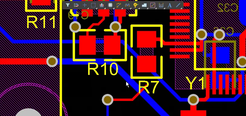
A 300dpi 3D screenshot taken from the PCB editor, then scaled down in an image editor to the maximum image size supported in this Web documentation editor.
Available 3D Outputs
Output Type |
From |
Notes |
| Screen capture | PCB editor | When the editor is in 3D Layout Mode, press Ctrl+C to take a screenshot of the current view. The 3D Snapshot Resolution dialog will appear, select the required Render Resolution and click OK to copy the image onto the Windows clipboard. From there, paste it into your preferred bitmap editor. |
| Export as an image | PCB editor | Select the File » Export » PCB 3D Print command. After selecting the location to save the image file, the PCB 3D Print Settings dialog will open, where you can set the Render Resolution, how you would like the board to be viewed, and the image format. |
| PCB 3D Print | OutputJob | Configured in the PCB 3D Print Settings dialog. In the OutputJob, map the output a New PDF container or directly to a printer. Position the board as required before generating output, then click the Take Current Camera Position and Take Current View Configuration buttons to generate a printout of what you can see on the screen. You can also create an image file, by mapping the Output Job to a Folder Structure Output Container. |
| PCB 3D Video | OutputJob | Configured in the PCB 3D Video dialog. In the OutputJob, map the output to a New Video container. Output can be in a variety of video formats. To generate this output you need to first define a PCB 3D movie in the PCB 3D Movie Editor panel. Refer to the Preparing a 3D PCB Video page to learn more. |
| PDF 3D | notes/PCB editor | Configured in the PDF3D dialog. In the OutputJob, map the output to a New Folder Structure. Requires Adobe Acrobat v9 or newer to support the 3D motion. Output can also include key frames from a PCB 3D Movie, if one has been defined. Refer to the Preparing a PDF3D File page to learn more. |
| Mechanical data | PCB editor | The completed board can also be exported in a number of different mechanical data formats (in its folded state for a rigid-flex board if required), ready to load into your MCAD design tool. Learn more about mechanical format import/export. |