An xSignal is a designer-defined signal path between two nodes; they can be two nodes within the same net or they can be two nodes in different nets.
xSignals are defined using the following methods:
-
Use the xSignals Multi-Chip Wizard. This will be the most common approach to creating xSignals and is described below.
Alternatively, the following methods are used by selecting objects of interest first, then choosing the appropriate command:
-
Create a single xSignal based on selected pads. Select the required start pad and end pad (these pads can be in different nets if there is a series termination component). Pads can be directly selected in the design space, or the PCB panel can be used in Nets mode to locate and select the pads (as shown in the image below). Once the pads are selected, either right-click on a selected pad in the design space then run the xSignals » Create xSignal from Selected Pins command, or right-click on one of the selected pads in the PCB panel and run the Create xSignal command. The new xSignal will be listed in the xSignals mode of the PCB panel.
When you are defining an xSignal based on selected pins (footprint pads), select only the start pad and the end pad before running the Create command.
The name of the new xSignal will be a combination of the two net names, separated by a hyphen. The xSignal name can be edited in the xSignals mode of the PCB panel.
The new xSignal can be added to an xSignal class, right-click in the xSignal Classes region of the panel to create a new class and add members to it.
-
Select the source component, then right-click on the selected component and choose the xSignal » Create xSignals between Components command from the context menu. The Create xSignals Between Components dialog will open, with the chosen source component selected. The dialog is described below.
-
Select one or more series components in the design space then right-click on one of the selected components and choose the xSignal » Create xSignals from Connected Nets command from the context menu. The Create xSignals From Connected Nets dialog will open. The chosen source component, and the nets connected to that component, will be selected. The dialog is described below.
-
There may also be situations where you wish to create an xSignal within an existing xSignal, in this situation the xSignal mode of the PCB panel can be used. Ensure that the Select option is enabled at the top of the panel, locate the current xSignal, select the required pads in the xSignal Primitives section of the panel, then right-click on one of the selected pads in the design space and use the method described in step 2 of this list to complete the process.

Select the two pads in the Nets mode of the panel, right-click on one of the selected pads then choose Create xSignal. Note that the pads are in different nets.
If the start and end pads are in the same net, an xSignal will take a name in the form <NetName>_PPn, where n is the next available integer used to distinguish multiple xSignals defined for that net. If the start and end pads are in different nets, an xSignal will take a name in the form <StartNet>_<EndNet>_PPn, where n is the next available integer used to distinguish multiple xSignals defined for that net combination.
Note that xSignals can also be created using the
Constraint Manager:
learn more.
xSignals Multi-Chip Wizard
The xSignals Multi-Chip Wizard is used to create xSignals between a single source component and multiple target components. The Wizard uses a component-oriented approach to identifying potential xSignals – you select a single source component, the nets of interest and the target components and the Wizard then analyzes all potential paths from the source component to the designation components, passing through series passive components and along any branches. As the designer, you then can choose the xSignals you would like to have generated and you can also create Matched Length design rules if required. The Wizard also can be used to automatically create xSignals and xSignal classes for a number of different common interface and memory circuits.
In this Wizard, an output pin is referred to as the Source, and the target input pin is referred to as the Destination.
The Wizard is also a multiple-run tool – from the overall master group of xSignals that you initially create on the xSignal Routes page, you can select a sub-set of these, define classes and rules, then return to the master group, choose another sub-set, define classes and rules for them, and so on.
One of the great strengths of the Wizard is the ease of working between the Wizard and the PCB editor. Click on an xSignal on any page of the Wizard and the pads and any routing are visually highlighted on the PCB.
At this stage, the Wizard does not support the automatic addition of T-junction identifiers, often referred to as tie-points or branch-points. If your design includes branched routing, it is suggested that you:
-
Tune the length from the source component to the passive component (such as a series termination resistor), if there are any.
-
Tune the length in each branch, from the T-Junction to the destination component.
-
If required, tune the remaining length between the passive component (or from the source if there are no passives) to the T-junction.
If you need to tune the lengths of just the branches, create a user-defined branch point by placing a single-layer, single-pad component within the routing at the T-junction. Refer to the
Defining the Branch Point in a Balanced T Pattern section below for more information.
To access the xSignals Multi-Chip Wizard, select the Design » xSignals » Run xSignals Wizard command from the main menus or right-click in the PCB layout and then select xSignals » Run xSignals Wizard. The opening page of the Wizard will be shown.

The opening page of the xSignals Multi-Chip Wizard
xSignals Multi-Chip Wizard Modes
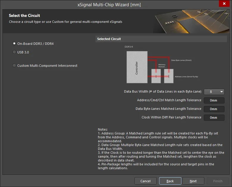
On the second page of the Wizard, you will be asked to select either Custom Multi-Component Interconnect, On-Board DDR3 / DDR4, or USB 3.0. The Custom Multi-Component Interconnect mode is used to define multiple xSignals between a chosen source component and multiple target components, while the On-Board DDR3 / DDR4 mode is used to create xSignals for your DDR3 or DDR4 memory. The USB 3.0 mode creates the xSignals, xSignal Classes, and Matched Length rules for each USB 3.0 channel. Select the appropriate mode for your needs.
The Custom Multi-Component Interconnect Mode
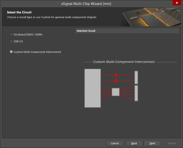
In this mode, the Wizard can be used to define multiple xSignals between a chosen source component and multiple target components. The Wizard uses a component-oriented approach to identifying potential xSignals; you select a single source component, the nets of interest and the destination components; it then analyzes all potential paths from the source component to the destination components, passing through series passive components and along any branches. As the designer, you then get to choose the xSignals you would like to have generated. As well as defining the end-to-end xSignals for multiple nets between components, the Wizard also allows you to create xSignals for sections of those end-to-end signals (from source output pin to series termination component, and from series termination component to destination input pin). Based on the settings you enable, the Wizard can also create xSignal classes and Matched Net Lengths design rules targeting those xSignals. When the Wizard is complete, you can then start the length tuning process.
The Wizard is configured over a number of pages. The number of pages depends on the circuit configuration. For example, if there are series terminators, there will be additional pages. The configuration of each page is described below.
Select the Source Component
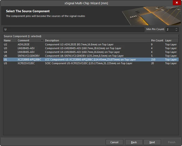
Use this page to select a single source component. Use the Filter and the Min Pin Count fields at the top of the grid to help locate the component of interest. The * and ? wildcards are supported.
The grids in this Wizard include a right-click shortcuts menu as well as the support of standard Windows multi-select keys. You can also use left-click or the Spacebar to toggle the checkbox of selected items.
Select the Source Nets
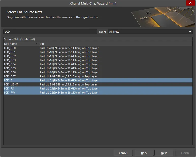
Select the nets of interest connected to the chosen source component. Use the Filter and Label fields at the top of the grid to help locate the nets of interest. Only pins with the listed nets will become the sources of the signal routes.
Select Destination Components
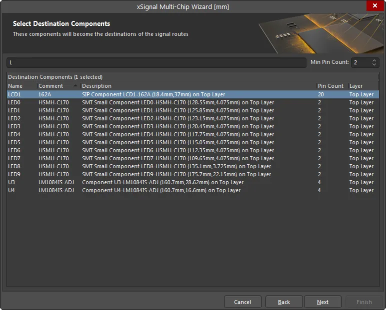
Select the desired destination component(s). Use the component Filter and the Min Pin Count fields at the top of the grid to help locate the component of interest.
When you click Next, the Wizard will identify all of the possible xSignals that can be created from the set of nets that have been selected between the chosen components. If the Wizard detects 2-pin components that have both of their pins connected to the chosen nets, these are automatically identified as series termination components and extra Wizard pages will appear later in the process.
xSignal Routes
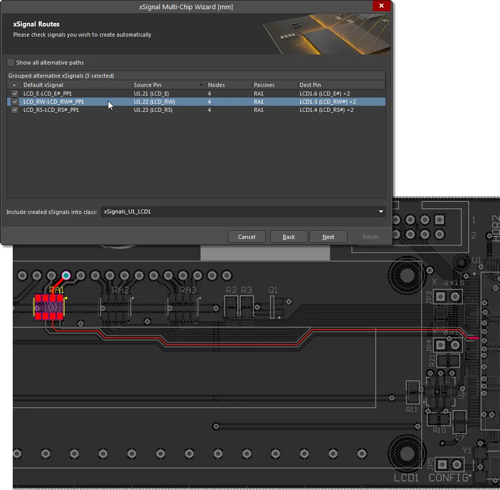
This page of the Wizard lists the proposed xSignals from each Source Pin through to each Destination Pin. Click on an entry to highlight that xSignal on the PCB.
After analyzing the net paths to identify potential xSignals, the Wizard will then attempt to reduce the set to only list combinations that you are interested in. These are the end-to-end xSignals; the above image shows them between the source and destination components selected in the previous pages of the Wizard. The image also shows that the Wizard has detected series termination component RA1 in each route. RA1 is actually a four resistor pack – in this situation, the Wizard will automatically create logical associations, assuming that each resistor runs across the pack, it will pair the nets that connect to pins that are opposite each other on the component.
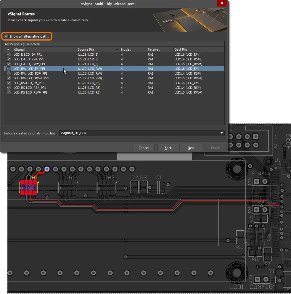
Because this assumption that the pins of each resistor are opposite each other might not always be correct, you can select any of the other available outgoing nets using the dropdown in the Dest Pin column. Alternatively, enable the Show all alternative paths option at the top of the grid to display all of the potential combinations of nets that could be used to generate xSignals. Enable the checkbox for each line for which you want to create an xSignal. The enabled xSignals will be added to the class displayed in the Include created xSignals into class field at the bottom of this page. Enter a new name or select one from the drop-down.
xSignals Length Tuning
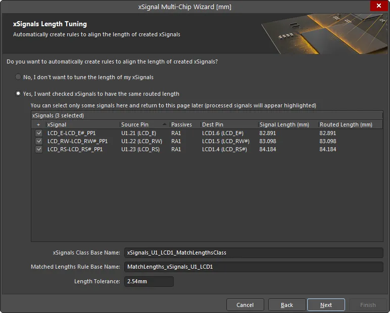
This page is used to automatically create a Matched Length design rule for the enabled xSignals. Enable only those xSignals you want to be targeted by this new design rule. If your design requires multiple rules with different requirements, you will be given the opportunity to define additional rules for those xSignals that have not yet had a rule defined later in the process. This first stage will also present the overall end-to-end xSignals. In later Wizard pages, you will have the opportunity to define design rules for the sections within the xSignals – for example, for the output pin to series termination resistor sections.
If you do not want to tune the length of your xSignals, enable No, I don't want to tune the length of my xSignals. No other options on this page will be available if this option is enabled. To be able to edit and access the other options, enable Yes, I want checked xSignals to have the same routed length.
The xSignals Class Base Name field is used to define a name for the currently selected xSignals. Enter a meaningful name, keeping in mind that you may be repeating this process for other xSignals. This set of xSignals will then be targeted by a design rule of the name you enter into the Matched Lengths Rule Base Name field, with the specified Length Tolerance.
Not sure which objects are being targeted? Click on one or more entries to highlight the signal path(s) in the PCB layout.
Source-to-Passives Length Tuning
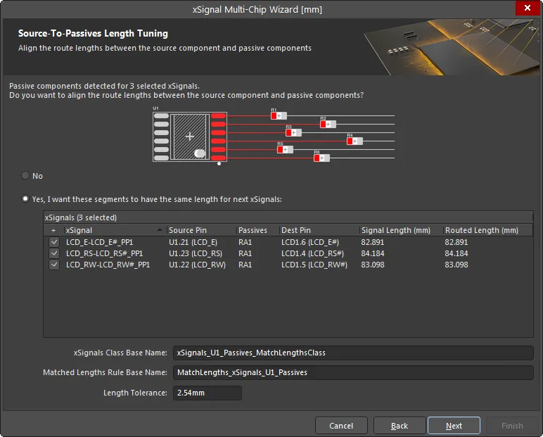
If the set of nets selected include series termination components, additional Wizard pages will appear that give you the opportunity to create additional xSignals and design rules for these sections of the nets. In the above image, you see that this page of the Wizard is being used to create a Matched Length design rule for the chosen xSignals that run from the Source pins to the termination components. If you require xSignals / an xSignal class / a design rule for these, enable the Yes, I want these segments to have the same length for next xSignals option, enable the required xSignals, and define the xSignals Class Base Name, Matched Lengths Rule Base Name and Length Tolerance. Additional xSignals will be created to use with this Matched Length rule.
Passives-to-Destinations Length Tuning
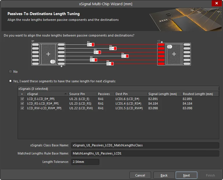
This page is used to create a Matched Length design rule for the chosen xSignals that run from the termination components to the Destination pins. If this is required enable the Yes, I want these segments to have the same length for next xSignals option, enable the required xSignals, and define the xSignals Class Base Name, Matched Lengths Rule Base Name and Length Tolerance. Additional xSignals will be created to use with this Matched Length rule.
Report and Continue
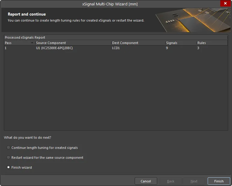
This page of the Wizard will detail the number of xSignals about to be created and the number of design rules about to be created.
At the bottom of the page you can choose to:
-
Continue length tuning for created signals – select if you disabled specific xSignals on previous pages and now need to go through the process of defining additional rules for those xSignals.
-
Restart wizard for the same source component – select if you want to discard these settings and restart the Wizard with the same components/nets selected.
-
Finish wizard – select if you are finished with this source component's xSignal and design rule creation.
xSignals are detailed in the xSignal mode of the PCB panel. Press the Delete key in the panel to remove selected xSignal classes or selected xSignals.
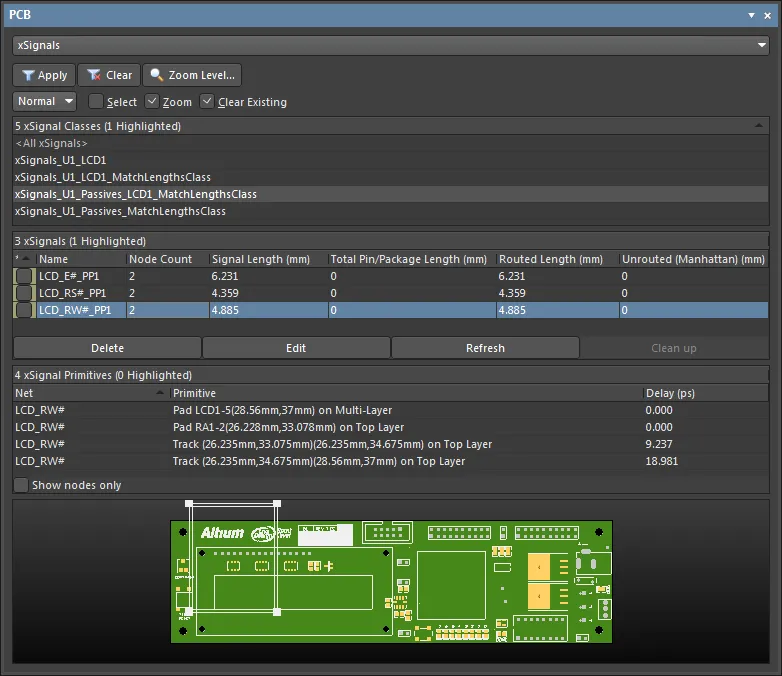
These xSignals are ready for length tuning. To get started, select the Interactive Length Tuning option ( ) from the main Route menu or the Active Bar.
You can easily remove a length tuning accordion. Click once on any segment in the accordion to select it, then press Delete.
Note that the existing track segments are broken at the start and end points when you place an accordion. Therefore, if you repeat this tune-then-delete process a few times, you can end up with a straight stretch of routing that is actually made up of many short track segments. To resolve multiple small track segments back into a single segment, run the Design » Netlist » Clean All Nets command from the main menus.
On-Board DDR3 / DDR4
In this mode, the wizard will automatically create the xSignals, xSignal Classes, Matched Length Groups, Diff Pair Matched Lengths rules and Fly-By topology for on-board DDR3/DDR4. The Wizard assumes that a fly-by routing topology will be used.
Select The Source Components
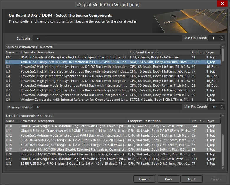
On this page, the Wizard identifies all potential source components and target components based on the designator prefix and the number of pins. Use the Controller/Memory Devices fields to filter components/memory devices and use the up/down arrows to set the Min Pin Count as required for both the Source Component and Target Components Then select a single source component and select the target component(s).
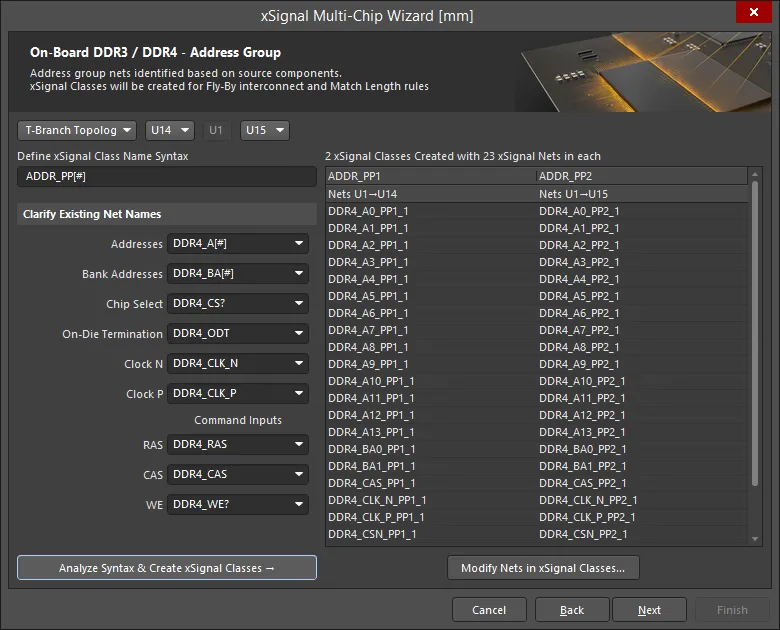
Address Group
The functionality of this page is as follows:
-
Fly-By Topology and T-Branch Topology options are supported. Select the required topology from the drop-down list.
-
If Fly-By Topology is chosen, the target devices are listed in the Point-to-Point order of the fly-by routing. The software will attempt to determine the order automatically. If the Wizard is run before component placement, then the point-to-point order will need to be set manually using the drop-down controls.
-
If T-Branch Topology is chosen (as shown above), half of the target devices will be shown before the source, and half after. Use the drop-down controls to order the target components as required.
-
Define xSignal Class Name Syntax:
-
The starting default is
ADDR_PP[#]
-
The
[#] represents the number of memory devices.
-
The
PP suffix can be changed if required.
-
The Wizard analyzes the components and looks for these suffixes in the design and displays the full name syntax, using the approach detailed below. Update these if they are not correct.
-
The objective here is to automatically find the nets that correspond to these functions Once the nets are found, the naming syntax is entered into the fields.
-
The nets between the components are then reviewed once the suffix is found the prefix is identified For example, the Wizard looks for
_A[#] to locate the Address lines.
-
If no nets are found with a suffix that begins with “_”, it then looks only for the text after the “_” Alternative separators, such as “-” or “.” are also checked for.
-
If the syntax cannot be automatically determined, you must define these fields. Use the drop-downs to select from the existing nets on the board.
-
Once the order and the naming syntax has been defined, click the Analyze Syntax & Create xSignal Classes button to build the list of xSignals. The Wizard will look at the syntax and how the components are connected and form the xSignal Classes that are displayed in the grid on the right side of the dialog. The number of Classes Created will match the number of memory devices.
-
The number of classes created (e.g., 4) and the number of xSignal nets in each class (e.g., 26).
-
The xSignals are grouped in a column for each xSignal class. A Matched Lengths design rule will be created for each class. The sub-headings in the table represent the source and target components for these xSignals.
-
If the automatically generated list is incomplete or incorrect, click the Modify Nets in xSignal Classes button to open and Edit xSignal Class dialog and manually add or delete nets to/from a class. Note that manual changes will be lost if the Analyze Syntax & Create xSignal Classes button is then clicked again.
Identifying the Data Group Nets
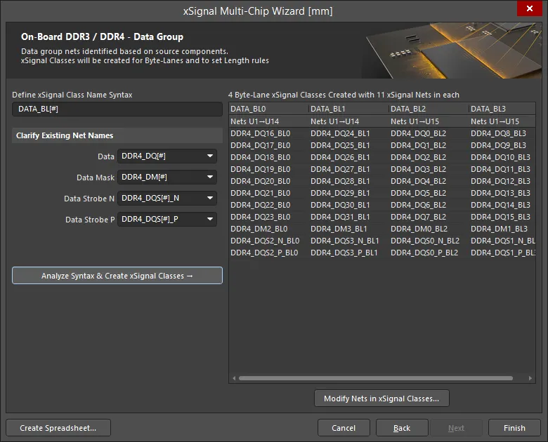
The final stage is to identify all of the nets that belong to the Data Group.
The functionality of this page is as follows:
-
User-defined xSignal Class name syntax:
-
The starting default is
DATA_BL[#]
-
The
[#] represents the number of Byte-Lanes, which is determined by the total number of Data lines divided by the Data Bus Width defined earlier.
-
The
BL suffix can be changed if required.
-
The Wizard analyzes the components and looks for these suffixes in the design then displays the full name syntax Use the drop-downs to update if these are not correct.
-
Once the naming syntax has been defined, click the Analyze Syntax & Create xSignal Classes button to build the list of xSignals. The Wizard will look at the syntax and how the components are connected and form the xSignal Classes that are displayed in the table on the right side of the dialog. The number of Classes created will match the number of Byte-Lanes connected to the memory devices. Above the table area, the number of classes created (e.g., 8) and the number of xSignal nets in each class (e.g., 11) are displayed.
-
Matched Lengths design rules are created for these xSignal Classes. The sub-headings in the table represent the source and target components for the Byte-Lane xSignals.
-
If the automatically generated list is incomplete or incorrect, click the Modify Nets in xSignal Classes button to open and Edit xSignal Class dialog and manually add or delete nets to/from a class. Note that manual changes will be lost if the Analyze Syntax & Create xSignal Classes button is then clicked again.
-
Click the Create Spreadsheet button to generate an XLS-format spreadsheet of the xSignals created by the Wizard.
xSignals and xSignal Classes Created
The Wizard automatically creates xSignals and xSignal Classes for the:
-
Address xSignals detailed on the Address Group page.
-
Data xSignals detailed on the Data Group page.
USB 3.0
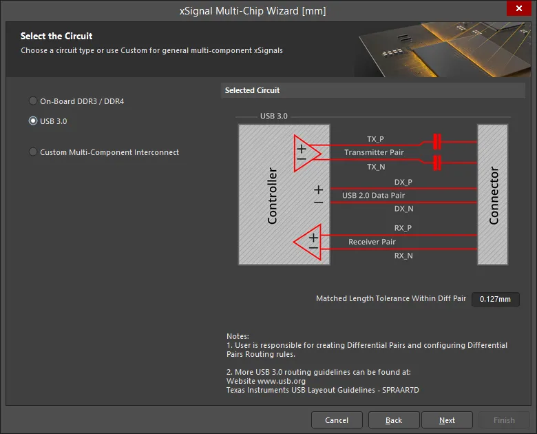
The Wizard can process all USB 3.0 channels between each controller–to-connector-pair specified by the user. The Wizard automatically evaluates Differential Pair nets connected to the controller, detecting those that span through to the connector. The span can include passive components and multiple nets. The Wizard identifies each of these pairs by an xSignal class, with each leg of the pair identified by a controller-to-connector xSignal.
Once you have selected USB 3.0, the page will include a setting for the Matched Length Tolerance Within Diff Pair. Enter a suitable value. This value is used for the design rule created by the Wizard and can be changed at any time in the PCB Rules and Constraints Editor. User-defined settings such as this are saved for future use.
For USB 3.0, each USB user port is referred to as a channel. As seen in the image, each channel includes three differential pairs: Transmit, Receive and Data.
For USB 3.0, the critical routing design requirement is to match the route lengths within each pair; between-pairs length matching is not as critical. Because of this requirement and the fact that the Matched Length design rule requires differential pairs to check lengths within a pair of nets, the Wizard will check for Differential Pair definitions and automatically create suitable differential pairs if there are none. The Matched Length design rule that the Wizard creates is then configured to check length matching Within Differential Pair Length. Note that the rule is configured to compare the leg lengths within the pair for the overall xSignal; it does not compare the leg lengths within each differential pair.
Select the Source and Target Components
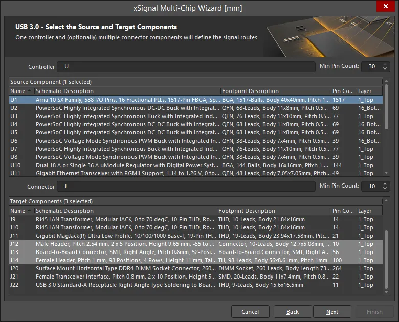
On this page, the Wizard identifies all potential source components and target connectors based on the designator prefix and the number of pins.
-
Set the filter prefix for the Controller designator, the Connector designator, and the Min Pin Count values as required.
-
Select a single source component.
-
Select the target component(s).
If you select multiple target components, you should check the xSignal and Net Naming Syntax for each of these components using the drop-down in the next page of the Wizard.
Channels Define Differential Pair Groups
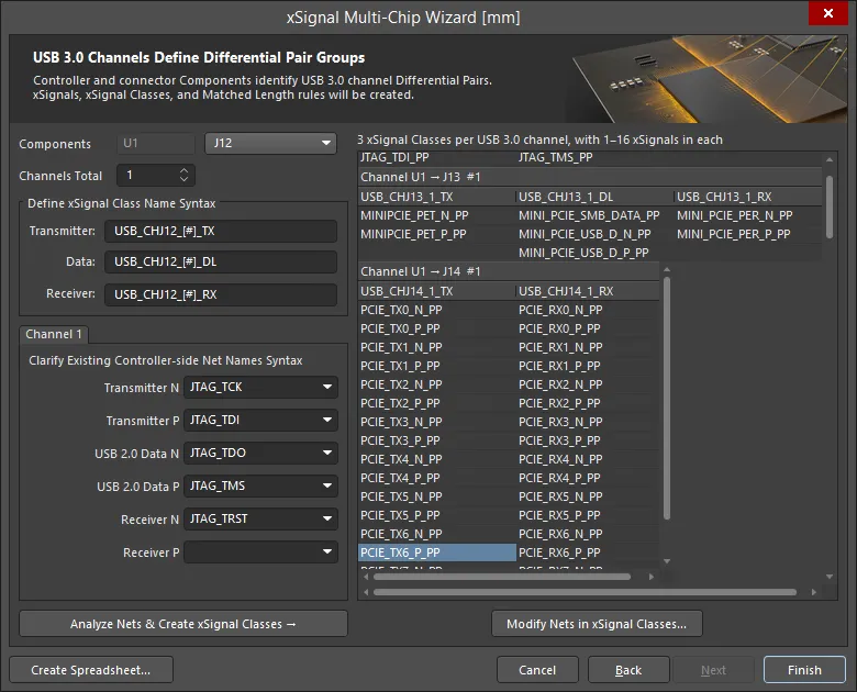
On this page, define a naming syntax that the Wizard can use to identify the relevant Transmitter, Receiver and Data pair nets, which are then included in xSignals. Each pair of xSignals is then clustered into an xSignal class and these classes are used to scope the Matched Length design rule.
The functionality of this page is as follows:
-
The designator of the Controller is displayed next to the Components label. Next to this, the drop-down includes all of the Connectors selected on the previous page of the Wizard.
-
The naming syntax options shown apply to each of the connectors listed in the drop-down. Select each in turn and check that the chosen naming syntax is complete and suitable.
-
As mentioned, for USB 3.0, each USB user-port is referred to as a channel. You can set the number of channels (Channels Total) from 1 to 32. Typically, each connector has a single channel.
-
Within each USB 3.0 channel there are three differential pair paths: Transmit, Receive and Data, which run from the Controller to the Connector. The Wizard will create an xSignal, spanning series components as required, for each positive net, and another xSignal for each negative net, and then an xSignal class to represent that Controller-to-Connector pair. The Define xSignal Class Name Syntax group is used to specify the names of these xSignal classes. The Wizard also creates suitable Differential Pairs, if there are none already defined.
-
Define xSignal Class Name Syntax – the xSignal classes that are created will be named as specified, with each channel assigned a numeric value in place of the
[#]. Enter your preferred string as required.
-
Channel <N> – these fields define the masks that are used to identify the relevant Transmitter / Receiver / Data net names.
-
The Wizard has a large template of predefined naming schemes that it checks and usually will populate these fields automatically. If it does not, select the correct name from the drop-down or type in a suitable net name syntax.
-
Once the naming fields are configured, click the Analyze Nets & Create xSignal Classes button.
-
The Wizard will create the xSignals, xSignal Classes, and Matched Length rules for all of the channels. Note that these are created each time you re-run the Wizard. Delete them if you plan to run the Wizard again.
-
The resulting xSignal Class names and their member xSignals are detailed in the grid.
-
Click the Create Spreadsheet button to generate an XLS-format spreadsheet of the xSignals created by the Wizard.
-
Click Finish to complete the Wizard.
Create xSignals Between Components Dialog
If you have a large number of xSignals to define, it is more efficient to use the Create xSignals Between Components dialog. Accessed via the Design » xSignals » Create xSignals command, the dialog presents Source and Destination components, and allows you to create one or many xSignals in a single operation.

Use the dialog to quickly identify and create multiple xSignals and add them to the required xSignal class.
The approach is to:
-
Select a single Source Component.
-
Select one or more required Destination Components.
-
Select the Source Net(s) of interest. All nets currently connecting to the chosen source component will be listed. For nets associated with a specific class, choose that class form the Net Class drop-down.
-
Click the Analyze button. The software attempts to identify potential xSignals that exist between the chosen source and destination components for the selected nets. All possible xSignals that include the chosen nets and run between the chosen source and destination components will be listed in the xSignals field. Note that the analysis algorithm follows the current topology of the chosen nets and this will influence the proposed xSignals.
The software can also search through series components, if required, by selecting the appropriate option in the Analyze drop-down: Search for direct connections, Through 1 series component, Through 2 series components, or Multipath coupled nets.
-
After analysis has been performed, potential xSignals will be listed in the lower region of the dialog, and all will be enabled for creation. Carefully check through the list of proposed xSignals, and enable only those that are required. Use commands available on the right-click context menu to toggle multiple entries.
-
Select the required class at the bottom of the dialog, or type in a name to create a new class. If no class is chosen, the xSignals are still created and you can add them to any xSignal class in the Object Class Explorer dialog (Design » Classes). Using classes can greatly simplify the creation and configuration of design rules.
-
Click OK to create the xSignals.
The dialog will close and you will be returned to the design space. The new xSignals will be listed in the xSignals mode of the PCB panel.
Use the filters above each list to quickly locate the components or nets of interest; wildcards are supported.
Create xSignals From Connected Nets Dialog
If you are creating xSignals that include series termination components, a good approach is to use the Create xSignals from connected nets command. The command is available whenever a component is selected either via Design » xSignals sub-menu from the main menus or the right-click xSignals sub-menu.
This command is designed to build xSignals outward from a selected series termination component, such as a resistor or capacitor. It supports both one or more discrete components, and one or more multi-instance pack-style components, such as resistor networks. After running this command, the Create xSignals From Connected Nets dialog will open.

Use the dialog to create xSignals that span across a selected series component. In this example, two possible xSignals were proposed, only one is going to be created.
The approach is to:
-
Select a single Source Component.
-
Select the Source Net(s) of interest. All nets currently connecting to the chosen source component will be listed. For nets associated with a specific class, choose that class form the Net Class drop-down.
-
Click the Analyze button. The software attempts to identify potential xSignals that exist for the chosen source components and for its selected nets. All possible xSignals will be listed in the xSignals field.
-
After analysis has been performed, potential xSignals will be listed in the lower region of the dialog, and all will be enabled for creation. Carefully check through the list of proposed xSignals, and enable only those that are required. Use commands available on the right-click context menu to toggle multiple entries.
-
Select the required class at the bottom of the dialog, or type in a name to create a new class. If no class is chosen, the xSignals are still created and you can add them to any xSignal class in the Object Class Explorer dialog (Design » Classes). Using classes can greatly simplify the creation and configuration of design rules.
-
Click OK to create the xSignals.
The dialog will close and you will be returned to the design space. The new xSignals will be listed in the xSignals mode of the PCB panel.
Use the filters above each list to quickly locate the components or nets of interest; wildcards are supported.
The Role of the Net Topology
When you define an xSignal, it is between two nodes or pads. However, when you select that xSignal in the xSignals mode of the PCB panel, it will actually follow the path of the connection lines that runs between those two pads, indicating that this is the path that the software assumes the xSignal will be routed. The reason it does this is because it is obeying the topology defined for that net. Net topology is defined by the applicable Routing Topology design rule; the default topology is Shortest.
The simple animation shows a CPU connected to four DDR3 memory chips, which is going to be routed using a fly-by routing strategy. The DRAM_A2 xSignal class contains four xSignals. First, the class is selected, then each xSignal is selected in turn. You can see how the xSignal path follows the topology of the net, which is currently set to the default - Shortest.

Because the net topology is currently set to Shortest, the xSignals are not following the required path from the processor to the memory chips.
If you plan on using the Create xSignals Between Components dialog, you will need to configure the topology of the net(s) to ensure the xSignal analysis algorithm understands the intended path of the routed xSignal.
xSignal Creation Commands
Apart from the Design » xSignals » Create xSignals command, there are other xSignal creation commands in the xSignals sub-menu when certain conditions are met.
Below is a summary of the commands and when they are available:
| Command |
Description |
| Create xSignal from selected pins |
Immediately creates a single xSignal. This command is available when there are two or more pads selected in the design space, and is the same command presented when you right-click on one of the selected pads.
|
| Create xSignals between components |
This command is available when components are selected in the design space. When it is run the Create xSignals Between Components dialog opens with the component(s) pre-selected. Ensure that the correct Source and Designation components are selected, then complete the Analysis/Creation process.
After launching the command, the Create xSignals Between Components dialog will open. Use the dialog to create your xSignals as follows:
-
The chosen source component will appear selected in the Source Component region.
-
Any other component(s) selected in the workspace will appear selected in the Destination Components region. If not, make your choice(s) now.
-
By default, all nets associated with the pads of the source component will be selected (in the Source Component Nets region). Adjust this selection as required.
-
Click the Analyze button - the software attempts to identify potential xSignals that exist between the chosen source and destination components, for the selected nets.
Note that the analysis algorithm follows the current topology of the chosen nets.
The software can also search through series components if required, by selecting the appropriate mode from the button's associated drop-down menu. Modes available are: Search for direct connections, Through 1 series component, Through 2 series components, and Multipath coupled nets.
-
All identified xSignals are listed in the xSignals region of the dialog. By default, all are selected for creation - adjust this as required.
-
You can optionally have the created xSignals associated to an xSignal class. Either choose an existing xSignal class or enter a name for a new class. You can leave the field blank if you wish; the xSignals can always be added as members to the required class at a later stage.
-
Click OK to create the xSignals. The dialog will close and you will be returned to the design space, which presents a filtered view showing the newly created xSignals. If an xSignal class was specified, this will be created (if not existing) and the xSignals associated to it.
|
| Create xSignals from connected nets |
Use this command when there are one or more series termination components to create xSignals for. Select the termination component(s), then run the command to open the Create xSignals from Connected Nets dialog, ready to complete the process of creating a set of xSignals. Use the dialog to create your xSignals as follows:
-
The chosen source component(s) will appear selected in the Source Component region.
-
By default, all nets associated with the pads of the source component(s) will be selected (in the Source Component Nets region). Adjust this selection as required.
-
Click the Analyze button - the software attempts to identify potential xSignals that exist for the selected nets emanating from the chosen component(s).
Note that the analysis algorithm follows the current topology of the chosen nets.
-
All identified xSignals are listed in the xSignals region of the dialog. By default, all are selected for creation - adjust this as required.
-
You can optionally have the created xSignals associated to an xSignal class. Either choose an existing xSignal class or enter a name for a new class. You can leave the field blank if you wish; the xSignals can always be added as members to the required class at a later stage.
-
Click OK to create the xSignals. The dialog will close and you will be returned to the design space, which presents a filtered view showing the newly created xSignals. If an xSignal class was specified, this will be created (if not existing) and the xSignals associated to it.
|
| Create xSignals |
Opens the Create xSignals Between Components dialog. This command is always available. Use the dialog to create your xSignals as follows:
-
Choose a source component in the Source Component region.
-
Choose one or more destination components in the Destination Components region.
-
All nets associated with the pads of the source component will be listed in the Source Component Nets region. Select the nets of interest.
-
Click the Analyze button - the software attempts to identify potential xSignals that exist between the chosen source and destination components for the selected nets.
Note that the analysis algorithm follows the current topology of the chosen nets.
The software can also search through series components if required, by selecting the appropriate mode from the button's associated drop-down menu. Modes available are: Search for direct connections, Through 1 series component, Through 2 series components, and Multipath coupled nets.
-
All identified xSignals are listed in the xSignals region of the dialog. By default, all are selected for creation - adjust this as required.
-
You can optionally have the created xSignals associated to an xSignal class. Either choose an existing xSignal class or enter a name for a new class. You can leave the field blank if you wish; the xSignals can always be added as members to the required class at a later stage.
-
Click OK to create the xSignals. The dialog will close and you will be returned to the design space, which presents a filtered view showing the newly created xSignals. If an xSignal class was specified, this will be created (if not existing) and the xSignals associated to it.
|
Defining the Branch Point in a Balanced T Pattern
One of the challenges of a Balanced T routing strategy is how to equalize the length of the trunks and the branches beyond the T points. The available nodes in the net are only at the pads, so it is not possible to define separate xSignals for the trunk, and from the branch point to the end of each branch. The branch points are indicated by the red dots in the image below.
One way to solve this problem is to add a single pin component to the net. Create a component with a single pad that is the size of the vias being used in the design. If the branch point component pad is single-layer, then it can also be used in combination with a blind or buried via, by placing it on the via's start or end layer, giving complete flexibility as to how the routing is created. If you only want to include the branch point component on the PCB, set the branch point component's Type to Mechanical to exclude it from the BOM, and prevent any synchronization issues with the schematic. If you plan on including the branch point component on the schematic, the component Type can be set to Standard (no BOM).

Balanced T routing can require matched lengths between intermediate branch points.
Because the branch point is a node in the net, you can now define xSignals for just the trunk, for each major branch, and for each minor branch, if needed. These can then be used to scope matched length design rules, giving the designer complete control over how finely the length matching is to be performed.
