
Creating Circuit Connectivity in Your Schematics

Altium Essentials: Creating Hierarchy
This content is part of the official Altium Professional Training Program. For full courses, materials and certification, visit Altium Training.
It is the components and how they connect to each other that create your unique, electronic circuit. In the schematic, you create the logical representation of your design by connecting the component pins together; to design the printed circuit board, you place the physical components and create the same connectivity with the routing.
Physical and Logical Connectivity
On the schematic, you can create that connectivity by drawing a wire from one component to another - this is referred to as physical connectivity.
You can also connect one pin to another by placing a short Wire and a Net Label on each component pin. The software identifies these two net sections and connects them to form a single net. This type of connectivity is referred to as logical connectivity.
Physical connectivity allows a user to follow each wire as they study the circuit, but a lot of wires can result in a dense and busy schematic. On the other hand, Net Labels reduce the amount of wiring, but the user must scan the sheet to find all potential connections. As the designer, you are free to decide which connectivity model best suits your design, including a mixture of both techniques.

Place wires to create physical connectivity or use net labels to create logical connectivity.
As well as creating logical connectivity within a schematic sheet, there are also objects for creating logical connectivity between schematic sheets. The way this connectivity is created will depend on how you structure your schematic: either as a flat design or as a hierarchical design. More about this below.

There are a number of different net identifiers that can be used to connect between sheets.
Connectivity Insight
The Altium Designer Connectivity Insight functionality (part of the Design Insight feature) displays an instant view of the connection relationships within a project. Shown as a document tree with optional schematic previews, the selectable elements provide a quick and visual way to navigate through a project's connectivity structure.
In its default setup condition, the Connectivity Insight feature displays:
- The related net connection information when the cursor hovers over a schematic connectivity object (wire, port, etc.).
- A tree-based connectivity preview map when Alt+Double-click is used on the object.
Adding to this capability is a feature that is accessed by hovering over an object that belongs to a signal net then pressing Ctrl+Alt. This opens a selectable tree view. Click the desired sheet in the tree to quickly jump to that document.

This feature can be enabled/disabled on the System - Design Insight page of the Preferences dialog by checking/unchecking the Mouse Hover option for the Document Tree entry.

Objects Used to Create Connectivity
The schematic editor includes the following objects that are used to create connectivity. Collectively these objects are referred to as net identifiers.
| Net Identifier | Function |
|---|---|
| Bus | Used to bundle a set of nets, for example, Data[0..7]. Nets must be named sequentially using a specific naming scheme (e.g., Data0, Data1,... Data7). This naming then dictates the Bus name, for example, Data[0..7]. |
| Bus Entry | Graphical device provided to support ripping two different nets from opposite sides of a bus line without creating a short between the two nets. Not required in other situations. |
| OffSheet Connector | Used to connect a net from one schematic sheet to another sheet (not within the same sheet). Only supports horizontal connectivity (flat designs). OffSheet Connectors have limited functionality when compared to Ports. |
| Net Label | A net identifier used to create connectivity to other Net Labels with the same name on the same schematic sheet. The net is automatically named by the Net Label. Net Labels can be placed on component pins, wires and buses. Note that Net Labels do not connect between sheets unless the project options are configured to use a Net Identifier Scope of Global. |
| Pin | Pins are placed in the schematic symbol editor to represent the physical pins on the component. Only one end of the pin is electrically active, which is sometimes referred to as the hot end of the pin. |
| Port | Used to connect a net from one schematic sheet to another. Connectivity can be vertical in a hierarchical design, or horizontal in a flat design (vertical and horizontal designs are explained below). Port names are used to name nets if the Allow Ports to Name Nets option is enabled in the Options tab of the Project Options dialog. in this situation, Ports will also connect within a schematic sheet, but they will not connect to Net Labels with the same name (learn more). |
| Power Port | Creates connectivity to every other power port of the same name, throughout the schematic project, regardless of the design structure. The net is automatically named by the Power Port. This net can be localized to a specific schematic sheet if required (learn more). |
| Sheet Entry | Placed within a Sheet Symbol, to create connectivity to a Port of the same name on that Sheet Symbol's child sheet. Sheet Entries are used as net names if the Allow Sheet Entries to Name Nets option is enabled in the Options tab of the Project Options dialog. |
| Signal Harness | Used to bundle any combination of nets, buses and lower-level signal harnesses. |
| Wire | A polyline electrical design primitive that is used to form electrical connections between points on a schematic. A Wire is analogous to a physical wire. |
Net Label

Net labels identify and electrically connect different points in a schematic.
Summary
Electrical connectivity between schematic component pins can be created by placing a wire between those pins. This is called physical connectivity since the pins are physically connected with a wire. Connectivity also can be created logically by using suitable net identifiers, such as net labels. As well as providing a human-friendly identifier for a net, a net label allows you to connect points on a circuit without actually physically wiring them together.
Availability
Net labels are available for placement in the Schematic Editor only in the following ways:
-
Choose Place » Net Label from the main menus.
-
Click the Net Label button (
 ) in the graphic objects drop-down on the Active Bar located at the top of the design space. (Click and hold an Active Bar button to access other related commands. Once a command has been used, it will become the top-most item on that section of the Active Bar.)
-
Right-click in the design space then choose Place » Net Label from the context menu.
-
Click the
button on the Wiring toolbar.
Placement
After launching the command, the cursor will change to a cross-hair and you will enter net label placement mode with a net label floating on the cursor:
-
Press Tab to open the Net Label mode of the Properties panel with the Net Name field selected and ready for editing; enter the new net name.
-
Position the net label so that its bottom-left corner touches the object to which you want to assign it then click or press Enter to place the net label.
-
Continue placing further net labels, or right-click or press Esc to exit placement mode.
Additional actions that can be performed during placement while the net label is still floating on the cursor and before the center point of the net label is anchored are:
-
Press the Tab key to pause the placement and access the Net Label mode of the Properties panel in which its properties can be changed on the fly. Click the design space pause button overlay (
 ) to resume placement.
- Press the X or Y keys to flip the net label along the X-axis or Y-axis.
- Press the Spacebar to rotate the net label counterclockwise or Shift+Spacebar for clockwise rotation. Rotation is in increments of 90°.
Considerations during placement:
- The electrical hotspot on a net label is the lower left corner, therefore, this corner must touch the wire, bus, or signal harness for a valid connection to be made.
- If the Net property of the net label is entered before it is placed and the value entered has a numeric ending, each subsequent net label will auto-increment this numeric value. This behavior is configured in the Auto-Increment During Placement options on the Schematic – General page of the Preferences dialog. For net labels, only the Primary field applies; the Secondary field applies when the object has multiple fields, such as a Pin.
Graphical Editing
The net label can be edited graphically using what is known as in-place editing. To edit a net label string in place, click once to select, pause then click a second time to enter edit mode.
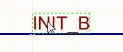 |
Click once to select the string. |
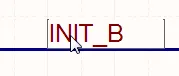 |
Pause, then click a second time to enter in-place edit mode. |
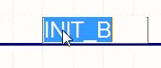 |
The string has been selected, ready to type in a replacement string. |
Once editing is complete, press Enter or click away from the string to exit in-place editing mode.
Notes
- Net labels create logical connectivity within a single schematic sheet; they do not create connectivity between schematic sheets. To do this, Ports must be used.
-
To negate (include a bar over the top of) a net label, use one of the following methods:
-
Include a backslash character after each character in the net name (e.g.,
E\N\A\B\L\E). -
Enable the Single '\' Negation option on the Schematic - Graphical Editing page of the Preferences dialog, then include one backslash character at the start of the net name (e.g.,
\ENABLE).
-
Include a backslash character after each character in the net name (e.g.,
- When individual nets form a bus, there are specific requirements as to how they are named. For more information, refer to the Bus page.
-
Net identifiers of different types do not automatically connect to one another even if they share the same name. For example, a net label named
AGNDwill not automatically connect to a power port namedAGND; a wire must be placed to connect them.
Net Label Properties

Location
-
(X/Y)
- X (first field) - the current X (horizontal) coordinate of the reference point of the object, relative to the current design space origin. Edit to change the X position of the object. The value can be entered in either metric or imperial; include the units when entering a value whose units are not the current default.
- Y (second field) - the current Y (vertical) coordinate of the reference point of the object, relative to the current origin. Edit to change the Y position of the object. The value can be entered in either metric or imperial; include the units when entering a value whose units are not the current default.
- Rotation - use the drop-down to select the rotation.
Properties
- Net Name - use the drop-down to select the net name or enter the name directly.
- Font - use the controls to select the desired font, font size, color, and attributes to bold, italicize, etc., if desired.
- Justification - select the justification by clicking on an arrow that corresponds with the desired justification, or the circle to center.
Off Sheet Connector

Off Sheet Connectors are used to create connections between schematic sheets.
Summary
An off sheet connector is an electrical design primitive. Off sheet connectors are used to connect nets across multiple schematic sheets that are descended from the same parent sheet symbol.
Availability
Off sheet connectors are available for placement in the Schematic Editor only in the following ways:
-
Choose Place » Off Sheet Connector from the main menus.
-
Locate and use the Off Sheet Connector command (
 ) on the Active Bar.
-
Right-click in the design space then choose Place » Off Sheet Connector from the context menu.
Placement
After launching the command, the cursor will change to a cross-hair and you will enter off sheet connector placement mode with an off sheet connector floating on the cursor:
- Press Tab to open the Off Sheet Connector mode of the Properties panel with the Net Name selected and ready for editing; enter the new net name.
- Position the off sheet connector so that its electrical hotspot (the end held by the cursor) touches the wire to which you want to connect then click or press Enter to effect placement.
- Continue placing further off sheet connectors or right-click or press Esc to exit placement mode.
Additional actions that can be performed during placement while the off sheet connector is still floating on the cursor are:
-
Press the Tab key to pause the placement and access the Off Sheet Connector mode of the Properties panel in which its properties can be changed on-the-fly. Click the workspace pause button overlay () to resume placement.
- Press the X or Y keys to flip the off sheet connector along the X-axis or Y-axis.
- Press the Spacebar to rotate the off sheet connector counterclockwise or Shift+Spacebar for clockwise rotation. Rotation is in increments of 90°.
Graphical Editing
The off sheet connector can be edited graphically using what is known as in-place editing. To edit an off sheet connector string in-place, click once to select, pause, then click a second time to enter edit mode.
 Click once to select the string.
 Pause, then click a second time to enter in-place edit mode.
 The string has been selected, ready to type in a replacement string.
The Off Sheet Connector can be edited in-place.
Once editing is complete, press Enter or click away from the string to exit in-place editing mode.
Notes
-
It is important to remember that although there are times when an off sheet connector and a sub-divided sheet symbol can be useful, they do have limitations. They will not properly form automatic component classes and these need to be recreated manually in the PCB, if you choose to use them.
-
To successfully connect a particular net across two or more sheets, the off sheet connectors on each sheet must be assigned to the same net.
-
Port Cross-References cannot be applied to off sheet connectors, therefore Ports should be used where possible.
Off Sheet Connector Properties

Location
-
(X/Y)
- X (first field) - the current X (horizontal) coordinate of the reference point of the object, relative to the current workspace origin. Edit to change the X position of the object. The value can be entered in either metric or imperial; include the units when entering a value whose units are not the current default.
- Y (second field) - The current Y (vertical) coordinate of the reference point of the object, relative to the current origin. Edit to change the Y position of the object. The value can be entered in either metric or imperial; include the units when entering a value whose units are not the current default.
-
Rotation - use the drop-down to select the rotation. Choices are:
0 Degrees,90 Degrees,180 Degrees, and270 Degrees.
Properties
-
Net Name - enter the net name.
-
Cross Ref - this field displays cross reference values that are applied to the offsheet connector.
-
Style - use the drop-down to select the default from the available choices:
LeftorRight. Click on the color box to access a drop-down from which you can select the default color.
General (Net)
Displays the properties of the nets assigned to the off sheet connector. Update as needed.
Parameters (Net)
- Selection buttons - click the desired objects to display in the grid.
- Add - use the drop-down to add the desired object(s) then define the values.
Power Port
 A placed Power Port
Summary
A power port is an electrical design primitive. It is a special schematic object used to define a power or ground net. Power ports allow you to conveniently indicate a power net at any location in the design, which can then be connected to pins or wires. Power nets of the same name automatically connect throughout the design, except in the following two situations:
-
If a Power Port is specifically wired to a Port object in a hierarchical design (i.e. in a design with the Net Identifier Scope set to
Hierarchicalor in a design that contains sheet entries on the top sheet and with the Net Identifier Scope set toAutomatic), then that power net becomes local to the sheet on which it is placed – net connections beyond the sheet must then be defined by the wiring of the Port/Sheet Entry combination (learn more). -
If the Net Identifier Scope is set to
Strict Hierarchical. This sets all power nets to be local within each sheet. Learn more about Setting the Net Identifier Scope.
Availability
Power ports are available for placement in the Schematic Editor in the following ways:
-
Click Place » Power Port from the main menus.
-
Click the
 button on the Wiring toolbar to place a bar-style power port, pre-assigned to the
 VCCnet. -
Click the
 button on the Wiring toolbar to place a power ground style power port pre-assigned to the
 GNDnet. -
Select a command in the power port drop-down in the Active Bar.
-
Click the
 button on the Utilities toolbar to access a drop-down providing an array of power port commands, including the various styles and several net-pre-assigned power ports.
-
Right-click in the design space then choose Place » Power Port from the context menu.
Placement
After launching the command, the cursor will change to a cross-hair and you will enter power port placement mode. A power port symbol will appear floating on the cursor.
- Position the object then click or press Enter to effect placement.
- Continue placing further power ports or right-click or press Esc to exit placement mode.
Additional actions that can be performed during placement while the power port is still floating on the cursor are:
-
Press the Tab key to pause the placement and access the Power Port mode of the Properties panel from where its properties can be changed on the fly. Click the design space pause button overlay () to resume placement.
- Press the Alt key to constrain the direction of movement to the horizontal or vertical axis depending on the initial direction of movement.
- Press the Spacebar to rotate the power port counterclockwise or Shift+Spacebar for clockwise rotation. Rotation is in increments of 90°.
- Press the X or Y keys to mirror the power port along the X-axis or Y-axis.
Graphical Editing
This method of editing allows you to select a placed power port object directly in the design space then change its location graphically. Power ports are fixed with respect to their size and shape. As such, editing handles are not available when the power port object is selected:
 A selected Power Port
- Click anywhere inside the dashed box then drag to reposition the power port as required. While dragging, the power port can be rotated (Spacebar/Shift+Spacebar) or mirrored (X or Y keys to flip along the X-axis or Y-axis).
-
The assigned net for a power port object can be edited in place by:
- Single-clicking the power port to select it.
- Single-clicking again (or pressing Enter) to enter the in-place editing mode. Sufficient time between each click should be given to ensure that the software does not interpret the two single-clicks as one double-click (which would open the Properties panel).
- To finish editing in-place text, press Enter or use the mouse to click away from the power port.
Power Port Styles
The following graphical styles of power port are available and can be set by editing the object's Style property in the Properties panel.
|
Arrow |
|
Bar |
|
Circle |
|
Earth |
|
GOST Arrow |
|
GOST Bar |
|
GOST Earth |
|
GOST Power Ground |
|
Power Ground |
|
Signal Ground |
|
Wave |


Notes
-
To negate a power port (include a bar over the top of its name), use one of the following methods:
-
Include a backslash character after each character in the net name (e.g.,
V\C\C\3\). -
Enable the Single '\' Negation option on the Schematic - Graphical Editing page of the Preferences dialog, then include one backslash character at the start of the net name (e.g.,
\VCC3).
-
-
When updating the PCB document from schematics, the Supply Nets design rule is suggested to be added to each net containing a power port.
Power Port Properties

Location
-
(X/Y)
- X (first field) - the current X (horizontal) coordinate of the reference point of the object, relative to the current design space origin. Edit to change the X position of the object. The value can be entered in either metric or imperial; include the units when entering a value whose units are not the current default.
- Y (second field) - The current Y (vertical) coordinate of the reference point of the object, relative to the current origin. Edit to change the Y position of the object. The value can be entered in either metric or imperial; include the units when entering a value whose units are not the current default.
- Rotation - use the drop-down to select the rotation.
Properties
-
Name - the name of the power port. Use the eye icon to show/hide the name.
-
Style - use the drop-down to select the style of the power object. The preview image updates according to your choice. Click the color box to choose the color.
-
Font - use the controls to select the desired font, font size, color, and attributes to bold, italicize, etc., if desired.
General (Net)
Displays the properties of the nets assigned to the power port. Update as needed.
Parameters (Net)
- Selection buttons - click the desired objects to display in the grid.
- Add - use the drop-down to add the desired object(s) then define the values.
Wire
 Wires are used to create electrical connectivity in a schematic.
Summary
A wire is a polyline electrical design primitive that is used to form electrical connections between points on a schematic. It is analogous to a physical wire.
Availability
Wires are available for placement in the Schematic Editor only in the following ways:
- Choose Place » Wire from the main menus.
-
Click the Wire button (
 ) in the drop-down on the Active Bar located at the top of the design space. (Click and hold an Active Bar button to access other related commands. Once a command has been used, it will become the topmost item on that section of the Active Bar).
-
Click the button on the Wiring toolbar.
- Right-click in the design space then choose the Place » Wire command from the context menu.
- Using the Ctrl+W shortcut.
Placement
After launching the command, the cursor will change to a cross-hair and you will enter wire placement mode. Placement is made by performing the following sequence of actions:
- Click or press Enter to anchor the starting point for the wire.
- Position the cursor then click or press Enter to anchor a series of vertex points that define the shape of the wire.
- After placing the final vertex point, right-click or press Esc to complete placement of the wire.
- Continue placing further wire objects or right-click or press Esc to exit placement mode.
- Use the Backspace or Delete keys to remove the last wire segment placed.
Placement Modes
When placing a wire, there are three 'manual' placement modes, two of which have Start and End sub-modes. The mode specifies how corners are created when placing wires and the angles at which wires can be placed. During placement:
-
Press Shift+Spacebar to cycle through the modes.
-
While in the
90 Degreeor45 Degreemode (known as true orthogonal modes), press Spacebar to cycle between the Start and End sub-modes. -
During placement, the current placement mode is displayed in the Status bar. You can change modes at any time during wire placement.
-
In modes other than
Any Angle, the line segment attached to the cursor is a look-ahead segment. The segment you are actually placing precedes this look-ahead segment.
 45 degree mode
 90 degree mode
 Any angle mode
 Auto Wire mode

Guided Wiring
Schematics have a definable electrical grid that makes it easy to define electrical connections between objects. As you are placing a wire, when the wire falls within the electrical grid range of another electrical object, the cursor will snap to the fixed object and a Hot Spot (blue cross) will appear.

The Hot Spot guides you to where a valid connection can be made and automatically snaps the cursor to electrical connection points.
The electrical grid can be defined on the General tab of the Properties panel in Document Options mode. It is recommended that you set the electrical grid to be slightly smaller than the current snap grid or it can become difficult to position electrical objects one snap grid apart.
Graphical Editing
This method of editing allows you to select a placed wire object directly in the design space and change its size and/or shape graphically.
When a wire object is selected, the following editing handles are available.
 A selected Wire ready for graphical editing.
- Click and drag A to reposition the end points of the wire.
- Click and drag B to move a wire vertex. The end points will remain anchored.
- Click and drag on a wire segment to grab that segment and reposition it. The end points and other vertices will remain anchored.
-
Right-click on a vertex point then choose the Edit Wire Vertex n command to access the Wire dialog with the entry for the
nthvertex selected ready for editing. Edit the vertex and/or other properties of the wire as needed. Refer to the Wire Properties section to learn more. - Click and hold on a vertex then press Delete on the keyboard to remove that vertex.
Information About Dragging
- While dragging, hotspots are used to provide a visual indication of where auto-junctions are going to be created.
- Unnecessary/redundant auto-junctions are removed after dragging has ceased.
Indication of New Auto-Junction Creation
Depending on the affected wiring, performing a drag operation may result in the creation of auto-junctions at new locations. To provide visual feedback on where these new junction instances will be, hotspots are used. Enable the use of these hotspots and their color for wires and buses in the Auto-Junctions region on the Schematic - Compiler page of the Preferences dialog.
Selecting and Removing
With the wire selected, click on a segment to individually select that segment. This wire 'sub-selection' is distinguished by the associated editing handles becoming red in color.
 Individual segment sub-selection.
The associated vertices for the segment can then be edited directly using the SCH List panel with any changes appearing immediately on the schematic.
You also can perform removal of selected wire segments with the tap of the Delete key. You can delete multiple segments across different wires - ensure that each is selected (Shift+Click twice on each subsequent segment to include it in the overall segment selection). Auto-junctions are also accounted for - allowing you to remove a segment of a wire up to that junction only (and including that junction if only two other wire segments would otherwise remain connected to it).
Autojunctions
A T-junction in a wire is automatically connected by a junction (Compiler-Generated Junction). If the Break Wires At Autojunctions option is enabled on the Schematic - General page of the Preferences dialog, an existing wire segment will be broken into two at the point where an autojunction is inserted. For example, when making a T-Junction, the perpendicular wire segment will be broken into two segments, one on each side of the junction. With the Break Wires At Autojunctions option disabled, the wire segment will remain unbroken at the junction.
Wire Properties

General (Net)
Displays the properties of the nets assigned to the wire.
Vertices
- Width - use the drop-down to select the desired width. Click the color box to select the desired color for the object.
-
Vertices Grid - lists all of the vertex points currently defined for the object in terms of:
- Index - the assigned index of the vertex (non-editable).
- X - the X (horizontal) coordinate for the vertex. Click to edit.
- Y - the Y (vertical) coordinate for the vertex. Click to edit.
-
Add - click to add a new vertex point. The new vertex will be added below the currently focused vertex entry and will initially have the same X,Y coordinates as the focused entry. Click
 to remove the currently selected vertex.
Parameters (Net)
- Selection buttons - click the desired objects to display in the grid.
- Add - use the drop-down to add the desired object(s) then define the values.
Compiler Generated Junction

The schematic compiler automatically adds junctions at each T-junction to complete the electrical connection.
Summary
A junction is an electrical design primitive. It is a small circular object used to join intersecting wires (or buses, or signal harnesses) on a schematic sheet. A Compiler generated junction is a junction that is automatically placed by the Auto-junctioning feature when two wires/buses/signal harnesses are connected in a T-type fashion, or when a wire/bus/signal harness connects orthogonally to a pin, power port or other electrical object.
Availability
This type of junction is placed automatically by the Schematic Editor's Auto-junctioning feature. As such, it is not a design object that can be accessed and placed by the user.
Placement
Compiler-generated junctions are placed automatically whenever a T-junction occurs during wiring, such as 2 wires/buses/signal harnesses meeting in a T, or a wire/bus/signal harness orthogonally crossing the end of a component pin or another electrical object, such as a Power Port.
Editing
A Compiler generated junction cannot be edited in the usual manner (via a dialog or graphically on the schematic sheet). The display properties of compiler generated junctions are configured on the Schematic - Compiler page of the Preferences dialog, as shown in the image below. Note that disabling the display of compiler generated junctions does not break the electrical connection at that junction point.
 in the Preferences dialog.") Configure the display options for compiler generated junctions (auto-junctions) in the Preferences dialog.
Configure the display options for compiler generated junctions (auto-junctions) in the Preferences dialog.
Indication of New Auto-Junction Creation
Depending on the affected wiring, performing a drag operation may result in the creation of auto-junctions at new locations. To provide visual feedback on where these new junction instances will be, hotspots are used. Enable the use of these hotspots, and specify their color - for wires and buses - also as part of your preferences.
 Control the display of predicted auto-junctioning during drag operations.

Example showing predicted new auto-junctions resulting from a drag operation.
Visual Indication of Connectivity Change
While dragging a component, it is possible to inadvertently drag a little to far, or off-course, resulting in an unintended auto-junction, and a potentially fatal change to the connectivity of a circuit. To provide a timely and graphical indication of the status of connectivity while performing a drag, a couple of icons are used:
![]() - OK - the drag operation is not altering the connectivity of the circuit.
- OK - the drag operation is not altering the connectivity of the circuit.
![]() - Alert - the drag operation is causing a change to the connectivity of the circuit.
- Alert - the drag operation is causing a change to the connectivity of the circuit.
The applicable icon is displayed near to the cursor as you drag.

Providing a visual warning that a drag operation will result in a change to connectivity.
Converting Cross Junctions
You can quickly convert a 4-way junction (created with wire or bus objects), into two adjacent 3-way junctions. To do this, select the Tools » Convert » Convert Cross Junctions command from the main menus. After launching the command, the Junctions Conversion dialog will appear. Use this dialog to determine the scope of the conversion (current document, project documents, or all open schematic documents), and whether all potential 4-way junctions are considered, or only those associated to selected wires/busses in the target documents. Once conversion options are configured as desired, clicking OK in the dialog will effect conversion.

The Junctions Conversion dialog
Options/Controls of the Junctions Conversion dialog
Scope
-
Sheet Scope - choose one of the following options to determine the scope of the update:
- Current Document - update the active schematic document only with changes to its current template.
- Project Documents - update the active schematic document as well as all other schematic documents in the active project with changes to their respective current templates. Schematics that are currently closed will be opened.
- Open Documents - update the active schematic document as well as all other open schematic documents (regardless of parent project) with changes to their respective current templates.
-
Selection - use the drop-down to choose the desired objects of the scope:
- Selected Objects - select only the objects that are selected in the chosen sheet(s) from Sheet Scope.
- All Objects - select all objects in the selected sheet(s) from Sheet Scope.
Options
- Miter Size - enter a value to define the size of the miter.
How The Design Structure Affects the Connectivity
Related page: Multi-sheet & Hierarchical Designs
If the design does not fit onto a single schematic sheet, it can be spread over multiple sheets. There are two distinct models for organizing and creating connectivity in a multi-sheet schematic: either as a flat design, which you can think of as one large schematic sheet that has been cut up into a number of smaller sheets; or as a hierarchical design, where the sheets are linked in a grandparent-parent-child type structure.
Multi-sheet designs are implemented by placing a Sheet Symbol on the parent sheet, which represents and links to the child sheet, as shown in the image below.
 lower-level sheets. In a flat design, this structure can only be one level deep; in a hierarchical design, there is no limit to the depth.")
Sheet Symbols represent (and link to) lower-level sheets. In a flat design, this structure can only be one level deep; in a hierarchical design, there is no limit to the depth.
Flat Design
Related page: Multi-sheet & Hierarchical Designs
A design is referred to as a flat design when the connectivity is created directly from one sheet to another sheet. It does not pass through Sheet Symbols on the parent sheet. In a flat design, the sheet symbols simply represent (and reference) the child sheets. All sheets in the design appear at the same level in the Projects panel because there is no hierarchy. Both of the images below show a flat design.
Flat designs are simpler to create. A flat design can include a top sheet with a Sheet Symbol for each child sheet, but this is optional since this top sheet is not used to create sheet-to-sheet connectivity. For a small design that only has two or three schematic sheets in it, you might decide that a top sheet does not add any value. Once the sheet count gets higher, a top sheet can help the reader understand the functionality of the circuit design from the way that the logical blocks (Sheet Symbols) are arranged on the sheet.
 and with a top sheet (right) - both are examples of a flat design.")

The same design, shown without a top sheet (left) and with a top sheet (right) - both are examples of a flat design.
In a flat design, the connections between the sheets can be created by Ports, Offsheet Connectors, Power Ports, and Net Labels, as shown in the image above with the magnifying glass. The recommended approach is to use Net Labels within each sheet and Ports to connect between sheets. Ports offer more features than Off-Sheet Connectors, including the ability to add Port Cross References, which adds a SheetName[GridReference] to each port, referring to a matching port on another sheet, as shown in the image below.
There is no limit to the number of sheets in a flat design.

Port Cross References have been added next to each Port indicating the target sheet and grid reference for the matching Port.
Hierarchical Design
Main page: Multi-sheet & Hierarchical Designs
A design is referred to as hierarchical when the sheet-to-sheet connectivity is from a Sheet Symbol down to the child sheet referenced by that Sheet Symbol. At the net level, the connectivity is created between a Sheet Entry in that Sheet Symbol and a Port with the same name as the sheet entry on the child sheet. This type of connectivity is also referred to as vertical connectivity since the sheet-to-sheet connectivity that is created is only up and down between a parent sheet and its child sheet.

In a hierarchical design, the net-level connectivity is from a Sheet Entry on the parent sheet down to a matching Port on the child sheet.
Hierarchical designs have two major strengths.
- The first is the ability to show the reader the functionality of the design in the way that the schematic sheets have been structured and presented as logical blocks (Sheet Symbols). The top-level schematic presents the design as a set of high-level functional blocks with the arrangement of the blocks reflecting their place in the traditional left-to-right, input-to-output flow of the overall circuit. These blocks can be further broken down into smaller blocks. if required, allowing the lowest level schematics that carry the components to have a relatively simple structure with a low component count. Because each sheet is relatively simple, the measured sheet size can be kept small, which is a big advantage when it comes to printing the schematic.
- The other major advantage is that it is generally much easier to trace a signal through a hierarchical design since the reader only needs to match a Sheet Entry on the parent sheet to the Port on the child sheet, and can trace the signal along the wiring within each sheet.
There is extra work in building up a hierarchical design. The Sheet Symbols require Sheet Entries and the top sheet must be wired to carry the signals from one Sheet Symbol to another. The software includes a tool to help keep the Sheet Entries synchronized with the child-sheet Ports (Design » Synchronize Sheet Entries and Ports for all Sheet Symbols, or right-click on a Sheet Symbol then choose Sheet Symbol Actions » Synchronize Sheet Entries and Ports for a single Sheet Symbol). It also includes tools to help break down a larger design into small chunks (Edit » Refactor » Move Selected Subcircuit to Different Sheet). To learn more about these restructuring and refactoring tools, refer to the Design Refactoring page.
A hierarchical design can be any depth and include any number of schematic sheets.
Multi-channel Design
Main article: Creating a Multi-channel Design
It is not unusual for an electronic design to include repeated sections of circuitry. It might be a stereo amplifier or a 64-channel mixing desk. This type of design is fully supported by a feature set known as multi-channel design. In a multi-channel design, you capture the repeated circuit once then instruct the software to repeat it by either placing multiple Sheet Symbols that all reference the same child schematic, or by configuring a single Sheet Symbol to repeat the referenced child schematic the required number of times. The compiled design is expanded out in the computer's memory with all components and connectivity repeated the required number of times in accordance with the user-defined naming scheme.
. On the right, the InputChannel.SchDoc is repeated eight times by the Repeat keyword.")

On the left, there are four Sheet Symbols all referencing the same child sheet (PortIO.SchDoc). On the right, the InputChannel.SchDoc is repeated eight times by the Repeat keyword.
The logical design that you capture is never actually flattened; it always remains as a multi-channel schematic. When you transfer it to PCB layout the physical components and nets are stepped out the required number of times, and you have full access to the cross-probing and cross-selecting tools available for Working Between the Schematic and the Board. There is also a tool in the PCB editor to replicate the placement and routing of one channel across all other channels, with the ability to easily move and reorient an entire channel. Refer to the multi-channel design document to learn more about multi-channel design.
A multi-channel design must be hierarchical because the software uses this structural model to instantiate the channels in memory.
Setting the Net Identifier Scope
Dialog page: Options for Project
The software uses the current setting of the Net Identifier Scope to establish how connectivity is created between the schematic sheets. The Net Identifier Scope is configured in the Options tab of the Project Options dialog (Project » Project Options).

Select the Net Identifier Scope mode to suit the structure of your design.
The behavior of the Global, Flat and Hierarchical options are shown in the images below.


Simple examples of how connectivity is created for each of the three main modes: Global, Flat, Hierarchical.
As well as the three options mentioned above, there is also an Automatic option. Generally, it is better to leave the Net Identifier Scope set to Automatic. The software will select the most appropriate of the three options based on the structure of the sheets and the presence/lack of Ports and Sheet Entries.
When set to Automatic, the software automatically selects which of the three main net identifier modes to use based on the following criteria:
-
If there are sheet entries on the top sheet,
Hierarchicalis used. -
If there are no sheet entries but there are ports present,
Flatis used. -
If there are no sheet entries and no ports,
Globalis used.
How Nets are Named
Each time you place a wire between component pins, you are creating connectivity. Every net in the design is given a name. If you have not placed a net identifier that can be used to name the net, the software names that net based on one of the pins in the net, for example, NetR7_1 as shown in the image below. If the component designator is changed at some stage, that system-generated net name is also changed and these changes must be passed between the schematic and PCB to keep everything in sync.

Nets without a net identifier are assigned a system-generated name based on one of the pins in the net.


Multiple Net Identifiers on a Net
You cannot have multiple Net Labels with different names on the same net within a schematic sheet. This situation will be detected and flagged as an error during validation. However, it is legitimate to have multiple net identifiers on a net on different sheets on which the net appears.
This ability allows you to:
- Change the name of a net at different levels in the hierarchy to better reflect its function on that sheet.
- Reuse a child schematic sheet without needing to rename nets on it.
Options for Controlling the Naming of the Nets
Dialog page: Project Options
Ultimately, each net can have only one name on the PCB (one PCB net cannot have two names unless you are intentionally connecting two nets with a Net Tie). The software automatically resolves nets with multiple names to have only a single name in the project, but it may not be the name you expect. There are a number of options available to control how the name is chosen in the Netlist Options section of the Options tab of the Project Options dialog. Refer to the Project Options dialog page for more details about each of the options.
A good approach to setting these options is to enable the Allow Ports to Name Nets and the Higher Level Names Take Priority options. Combine these with sensible usage of Net Labels on significant nets on each sheet to ensure that all of the important nets, including those that traverse sheets, are named, and that the names assigned on the higher-level schematics are used on the lower-level schematics.
Two Separate Nets That Have the Same Name
Another net naming issue that can arise is when the same net name has been used on different schematic sheets to label different nets. This will be detected during validation by the Duplicate Nets error check. You cannot transfer a design to the PCB with this condition present. Those two separate nets will be merged into a single PCB net during design transfer.
This situation can be resolved by enabling the Append Sheet Numbers to Local Nets option on the Options tab of the Project Options dialog. With this option enabled, all local nets have the value of the SheetNumber parameter appended to their name, as shown in the images below.

Since the net label Input has been used on multiple sheets, the Append Sheet Numbers to Local Net option has been enabled to prevent a Duplicate Nets error.
The effect of this can be seen by clicking on the complied sheet tab (right image), note that _2 has been appended to the net name.
Intentionally Connecting Two Nets
There are situations when you need to intentionally connect two different nets. This is not a simple naming issue. It is when two nets need to be shorted as a design requirement. An example could be when you need to connect an Analog ground and a Digital ground in a controlled way.
This is achieved by connecting the two nets through a Net Tie component. A Net Tie component is nothing more than a controlled short circuit, allowing you to decide the location on the board where the nets connect. On the schematic, the Net Tie component has two or more pins, with each pin connected to one of the nets to be shorted. The Component Type property of the component is set to Net Tie, as shown below.

A Net Tie component being used to route a single clock to two FPGA clock pins on the schematic.
Note that the pins are not wired to each other on the schematic (they are not shorted on the schematic), but they are connected together within the PCB footprint.
On the PCB side, the footprint has the same number of pads as the schematic symbol has pins with copper between them. In the example image below, this is achieved by connecting two square pads with a length of track. This is done within the footprint in the PCB library editor. The PCB Component Type property is also set to Net Tie.
The software automatically ignores short circuits created within a Net Tie PCB component, therefore, a DRC error is not created.
 in the Net Tie footprint are shorted with a track.")
The same Net Tie component on the PCB; the pads (selected) in the Net Tie footprint are shorted with a track.
When a Net Tie component is used to connect two different nets, each net retains its own name throughout the schematic and on the PCB.
Power Nets
The default behavior of the settings is to assume that power nets are global, i.e. you want them to be available on every schematic sheet. To access a power net, place a Power Port with the required net name, then wire the components to that power port. When the design is compiled, all of the pins connected to each power net will be connected, across all of the sheets in the project.

It's the net name that determines to which net a power port is connected, not the Style of the symbol - the three highlighted power ports all connect to the GND power net.
Localizing a Power Net - Globally
As mentioned previously, power nets can be localized to each schematic sheet in a hierarchical design by selecting the Strict Hierarchical option for the Net Identifier Scope. This approach localizes all power nets on every sheet, so they must be manually wired together, using the same approach as signal nets. If they are not wired together, there will be a Duplicate Net Name error for each power net present on each schematic sheet. You will also need to adjust the Connection Matrix settings to allow Ports to be connected to Power Ports.

If the Net Identifier Scope is set to Strict Hierarchical, every power net must be wired to every sheet on which they are used.
Connecting a Localized Power Net Between Sheets
You connect a power net that has been localized in a hierarchical design in the same way as any other net, from a port on the child sheet to a sheet entry in the sheet symbol on the parent sheet. Note that for power nets, this technique only supports individual power nets, not power nets that have been bundled into a bus ( ).
).
If you are creating a multi-channel design and want to supply a unique, individual power net to each channel using the Repeat statement (as shown below), this is supported because you are only passing one net into each channel through the sheet entry-port combination. As long as the design only attempts to connect an individual power net from parent to child through each sheet entry-port combination, it will netlist correctly.
 Localized power nets can be distributed to each channel in a multi-channel design, if they travel up-down the hierarchy as individual nets, not as a bus.
Localizing a Power Net - Individually
A specific power net in a hierarchical design (i.e. in a design with the Net Identifier Scope set to Hierarchical or in a design that contains sheet entries on the top sheet and with the Net Identifier Scope set to Automatic – learn more about Setting the Net Identifier Scope) can also be localized on a specific sheet by wiring the Power Port to a Port on that schematic sheet.

Here the 3V3 power net has been localized for just this sheet, so it must also be manually wired on the parent sheet. The GND and 5V nets remain as global power nets.
Dynamic Compilation
Related page: Validating Your Design Project
When you connect two pins with a wire, you are drafting your design intentions, not creating an actual net. The net is not created until the project is compiled. As well as extracting details about the components and how they are connected, compiling also extracts detailed component and design parametric information. The compiled model of the project is referred to as the Unified Data Model.
The design data model is incrementally updated after each user operation through dynamic compilation - creating what is referred to as the Dynamic Data Model (DDM). There is no manual compilation of the project involved, it is all done automatically. The design connectivity model is incrementally updated after each user operation, courtesy of dynamic compilation. For a design project, the automatic compilation process performs three functions:
- Instantiates the design hierarchy.
- Establishes net connectivity between all the design sheets.
- Builds an internal Dynamic Data Model (DDM) of the design.
This ensures that any design changes that are made are immediately reflected in the Navigator and Projects panel.
In order to check for logical, electrical, and drafting errors between the DDM and compiler settings, you must validate the project. This command is accessed by choosing the Project » Validate Project command from the main menus or by right-clicking over the entry for a project in the Projects panel, and choosing the Validate Project command from the context menu.
Any violations that are detected by the Compiler will be listed as warnings and/or errors in the Messages panel. The Compiler uses the options defined on the Error Reporting and Connection Matrix tabs of the Project Options dialog (as applicable to the project type), when checking the source documents for violations.
The Dynamic Data Model
A fundamental element of the software is the Unified Data Model (UDM). Through the automatic instance of dynamic compilation, a single, cohesive model is created, which sits central to the design process. Data within the model can be accessed and manipulated by the various editors and services within the software including the schematic and the PCB. Rather than using a separate data store for each of the various design domains, the UDM is structured to accommodate all information from all aspects of the design, including the components and their connectivity. This single, cohesive model that sits central to the design process is created as a result of dynamic design compilation. It means that the Unified Data Model is available from the moment a project is opened and should not require additional manual compilation – a true Dynamic Data Model (DDM). Therefore, the model is incrementally updated (compiled) after each user operation. You can freely place, wire, rearrange, rename, add, and delete content from your schematic design.
The PCB design compilation process is managed by code outside of the schematic and PCB editors. There are a number of advantages to this approach, with the biggest being that the Unified Data Model of the design sits outside of the individual schematic and PCB editors. The UDM includes detailed descriptions of every component in the design and how they connect to each other.

The software manages the connective data across the schematic and the PCB.
The following locations and operations do not require any additional manual actions in terms of design compilation as compilation is dynamic:
- Navigator and Projects panel
- ActiveBOM
- Performing ECO
- Cross-probing
- Net color highlighting
- Pin swapping
- Component cross reference

So how do you interact with the Unified Data Model, for example, to trace a net through the design? You do that through the Navigator panel.
Examining the Connectivity
Panel page: Navigator panel
If the design is large and spread over many sheets, it can become difficult to follow and verify the connectivity in the design. To help with this process, you can use the Navigator panel is used. The panel gives a view of the entire, compiled design.
The basic approach to using the panel is to:
-
Set the browsing behavior by clicking the
 button at the top of the panel to open the Preferences dialog and enable your preferred Highlight Methods. Alternatively, right-click on the object of interest in the panel, and use the menu options to configure the navigation behavior, as shown in the image below.
-
Set the scope of your browsing in the Documents for region of the panel to browse the entire design select
Flattened Hierarchy. - Click on a component in the Instance section of the list to jump to that component, expand the component to locate, or jump to a pin.
- Click on a net or bus in the Net /Bus section to jump to that net or bus.
- Hold the Alt key as you click to jump to that object on both the schematic and the PCB.
.")
Click on a component or net in the Navigator panel to locate that component or net, and trace the connectivity through the design. Right-click to access display options. Hover the cursor over the image to show navigating to a component on the schematic and the PCB simultaneously (hold Alt as you click in the Navigator panel to include the PCB object).
Navigating Components on the Board
As well as locating components on the schematic and the PCB (if Alt is held) from the Navigator panel, you can also navigate pins/components/nets/buses/harnesses on the PCB, directly from the schematic.
For example, as you click to locate a component on the schematic, you can also locate that same component on the PCB.
To do this:
- Enable the Selecting option in the Highlight Methods, and also your preferred options in the Cross Select Mode section in the System - Navigation page of the Preferences dialog.
- Enable Cross Selection (Tools » Cross Select Mode) in both the schematic and PCB editors.

These options configure the navigation and cross selection behavior.
Now as you select pins/components/nets/buses/harnesses on the schematic, those objects will also be selected on the PCB, as shown in the image below.

Selecting components and nets on the schematic, those objects are also selected on the PCB. Cross selection also works from the PCB to the schematic.
Searching for Components and Nets in the Project Structure
Navigate through the structure in the panel to find a Component or Net of interest, and then double-click on the object to show the instance(s) of that object in the project's schematic documents. Use the options on the System - Navigation page of the Preferences dialog to specify the object highlighting behavior (Zoom, Dim, Select, etc.).

Project object navigation is also available in the Navigator panel, which provides a detailed hierarchical structure of design objects and their associated data. The System - Navigation preference settings determine the object highlighting the behavior of both the Project and Navigator panels.
Connection Highlighting
The connectivity navigation option shows the connection relationships of an object selected in the Projects panel. Double-click on an entry, such as Net, in the panel's object hierarchy list to highlight its interconnections in the schematic.
The preview feature is enabled by the Connectivity Graph option in the Highlight Methods section of the System – Navigation page of the Preferences dialog. Select the additional Include Power Parts option to also see the connectivity of power objects that are associated with the selected object.

Global Net Highlighting
The net connectivity throughout a design can be highlighted in all schematics by holding the Alt key when selecting a net by clicking on a wire (Alt+Click). All schematic instances of the net are highlighted, while other objects are dimmed, to visibly indicate the signal/power propagation in the design using one simple action.
Net highlighting is cleared by clicking in free space, and its behavior is determined by the Highlight Methods settings on the System - Navigation page of the Preferences dialog. Note that unchecking the Dimming option will disable the net highlighting feature.
Configuring the Color of Nets
Main page: Applying Color to the Nets
To help make the schematic more readable and make it easier to work with nets and routes in the PCB editor, color can be applied to schematic wiring, and the PCB nets and routes.
A highlight color can be applied to a net or a bus in the schematic editor using the commands in the View » Set Net Colors sub-menu, as shown in the image below. These colors can be transferred to the PCB editor at any time, via the Update PCB command.
In the PCB editor, the default color and visibility of the Connection Lines is configured in the System Colors section of the PCB View Configuration panel. Note that this default color is applied when the nets are created (during initial design transfer from schematic), the color of existing connection lines will not change if this option is changed.
In the PCB editor, the color applied to each net is displayed in the Nets mode of the PCB panel. Look for the color behind the checkbox next to the net name, as shown in the bottom right corner of the image below.
The color is always applied to the unrouted nets (connection lines). To display the color on the routed nets, enable the checkbox next to the net name in the PCB panel, and configure the display options in the Board Insight Color Overrides page of the Preferences dialog. In the image below, the override color Base Pattern is set to Solid, and the Zoom Out Behavior is set to Override Color Dominates.
 The net colors applied in the schematic are transferred to the PCB by the Update PCB command. Configure the PCB Color Override features to control how they are displayed on the board.
Changing the Color of the PCB Nets
It is not always possible to apply color to the schematic wiring and transfer it to the PCB. In this situation, color can still be applied to connection lines and routing in the PCB editor. To change the color of a net after the design has been transferred, double click on the net name in the Nets mode of the PCB panel. The color of an individual net can be edited in the Edit Net dialog.
To change the color of multiple nets, use the Nets mode of the PCB panel:
- Use standard Windows multi-select techniques (Shift+click or Ctrl+click) to select multiple net classes or multiple individual nets.
- Right-click on a selected object and choose the Change Net Color command from the context menu, to assign a new color to the selected nets.
- Right-click a second time and choose Display Override » Selected On, to enable the color override feature for the selected nets.

Improve the visibility of nets by changing the color of their connection lines, and enabling the display override feature.