Parent page: Altium Concord Pro
Altium Concord Pro facilitates the uni- or bi-directional synchronization of component data with your enterprise systems. A configuration file allows you to specify the direction of synchronization and therefore which parameters are mastered in which system. Component data synchronization between Concord Pro and the target enterprise system uses a built-in synchronization process, which may be manually triggered or set as a timed repeating event.
Altium Concord Pro does not offer full PLM integration - this level of integration is only available through
Altium NEXUS.
Note that synchronization of Part Choice data is unidirectional - from the enterprise system to Altium Concord Pro only.
An Altium Concord Pro installation includes a CSV Component database importer tool that can be used to bring component data into Concord Pro from a file exported from another system (PLM, ERP, or otherwise). In addition, direct support is provided for the following enterprise systems:
- PTC Windchill® PLM (11.0 M030)
- Arena® PLM
- Oracle® Agile™ PLM
Interface configuration is performed through Concord Pro's browser interface, with the connection setup and parameter mapping defined within an XML-based configuration file (uploaded to the server).
When the synchronization process first adds a component's data in the target system, the generated item number is passed back to the component in Concord Pro as a PlmPartNumber parameter. This acts as the key parameter when synchronizing data between Concord Pro and the enterprise system instance. In addition, the configuration can be arranged so that item parameters/attributes on the enterprise system side will update properties in the Concord Pro server (configurable per field), without having to formally release a new revision of that Component Item.
CSV Uploader
An Altium Concord Pro installation includes a CSV Component database importer tool that can be used to bring component data into Concord Pro from a file exported from an enterprise system. Implemented as a configurable batch (*.bat) file, the desktop tool imports component data from a target spreadsheet file (*.csv) into the server as determined by existing server templates or a dedicated configuration file.
The command line tool can be found in the \Program Files (x86)\Altium\Altium Concord Pro\Tools\CSVImport folder of the Concord Pro installation. See the csv-import.bat for information on the command line syntax used with the tool, or simply execute the batch file without attributes for more detailed information.
Notes:
- The tool and its supporting Java runtime folder (
JRE8) may be copied to and run in any location, including on a different networked machine to the one hosting Concord Pro.
- The tool may need to be run with elevated (Administrator) privileges, depending on where it is located.
- The tool syntax is case sensitive, as are references in Server Templates and any configuration files used.
Source file format:
The CSV data importer tool requires the source comma-delimited CSV file to use UTF-8 character encoding. If the file uses other encoding formats such as ANSI or UTF-8-BOM, the importer will not parse extended characters (such as µ) correctly, or may not accept the *.csv source file.
If creating a basic CSV file for testing purposes, note that some versions of Windows' Notepad do not save in a compatible UTF-8 format. If in doubt, an alternative text editor such as Notepad++ can be used to create and save UTF-8 encoded files, and is also useful for checking the encoding format of *.csv files exported from a source enterprise system.
Auto mode
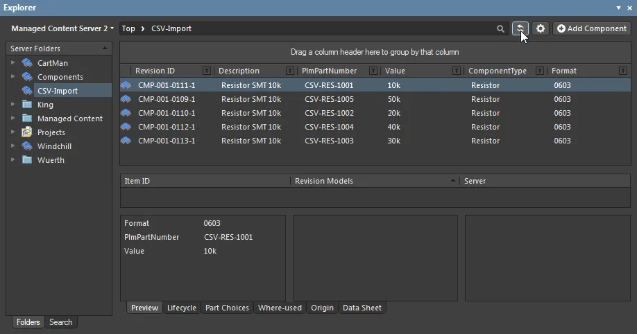
When used without applying a configuration file (option –c) the CSV Uploader tool process will attempt to match the target CSV filename (say, Resistor.csv) with a server Component Template that supports that Component Type (Resistor). The found Template will determine the Revision, Lifecycle and Default Folder (server target) for the imported data. Note that the minimum data required for the source CSV file is the PART_NUMBER parameter column and its matching Values.

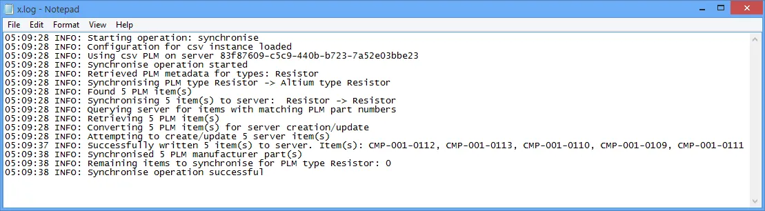
The csv-import utility tool provides general progress information in the console window as it runs, and can also produce a log file as specified by the command syntax (-l). If component manufacturer part parameters are present in the CSV file (by default; MFR_PART_NUMBER and MFR_NAME), matching Part Choice entries are created in the server.
The optional log file provides details of a successful import process – if the process fails, a log file is not generated.
Multiple Manufacturer Part Choices
The manufacturer part data for CSV component entries is sourced from their MFR_NAME and MFR_PART_NUMBER column values, which are ultimately processed as Part Choices for the imported server components.
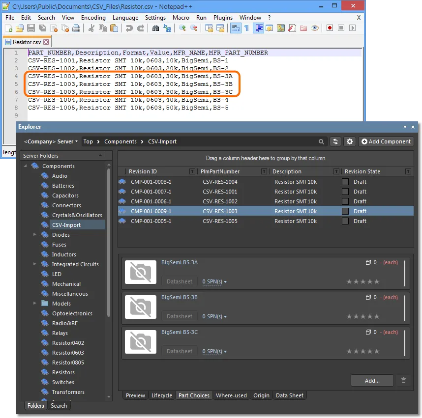
The CSV Importer also accommodates multiple sets of manufacture part data for a given component through a repeated structure in the source CSV file, where additional component entries are included for each manufacturer part data variation. For example, if the source component CSV-RES-1003 has three related part numbers from the company BigSemi – BS-3A, BS-3A, and BS-3A – then the CSV source file would include, at a minimum, the following entries:
PART_NUMBER	MFR_NAME	MFR_PART_NUMBER
CSV-RES-1003	BigSemi		BS-3A
CSV-RES-1003	BigSemi		BS-3B
CSV-RES-1003	BigSemi		BS-3C
When this component data is imported to the server, a single component item is created for part CSV-RES-1003, but with multiple Part Choices entries derived from the above CSV data.
Configured mode
The tool’s more advanced mode uses an XML configuration file to specify file-to-server parameter mapping for the import process. For the example shown here this might be say, mapping the source Value parameter to Resistance in the server, and the Format parameter to Package.
To obtain a base configuration file that can be modified to suit, run the tool with the generate configuration file setting (-g). This will create the specified XML file with parameter key/value pairs extracted from the source CSV file, and the Revision, Lifecycle and target folder setting from the matched Template. For example:
csv-import.bat -s http://HPZ600:9780 -u admin -p admin -g MyConfig.xml -i C:\Users\Public\Documents\CSV_Files\Resistor.csv
Edit the Attribute Values in the ToAltium section of the MyConfig.xml configuration file (for the Resistor entity) to map as required.
Mapping edits for this example
For the example shown here, the related Attributes would be changed from:
<ns2:Attribute attributeType="revision">

  <ns2:Key>Format</ns2:Key>

  <ns2:Value>${attribute.Format}</ns2:Value>

</ns2:Attribute>

<ns2:Attribute attributeType="revision">

  <ns2:Key>Value</ns2:Key>

  <ns2:Value>${attribute.Value}</ns2:Value>

</ns2:Attribute>
...to:
<ns2:Attribute attributeType="revision">

  <ns2:Key>Package</ns2:Key>

  <ns2:Value>${attribute.Format}</ns2:Value>

</ns2:Attribute>

<ns2:Attribute attributeType="revision">

  <ns2:Key>Resistance</ns2:Key>

  <ns2:Value>${attribute.Value}</ns2:Value>

</ns2:Attribute>
The configuration file is then used with the tool (option –c) to perform the required mapping:
csv-import.bat -s http://HPZ600:9780 -u admin -p admin -c MyConfig.xml -i C:\Users\Public\Documents\CSV_Files\Resistor.csv
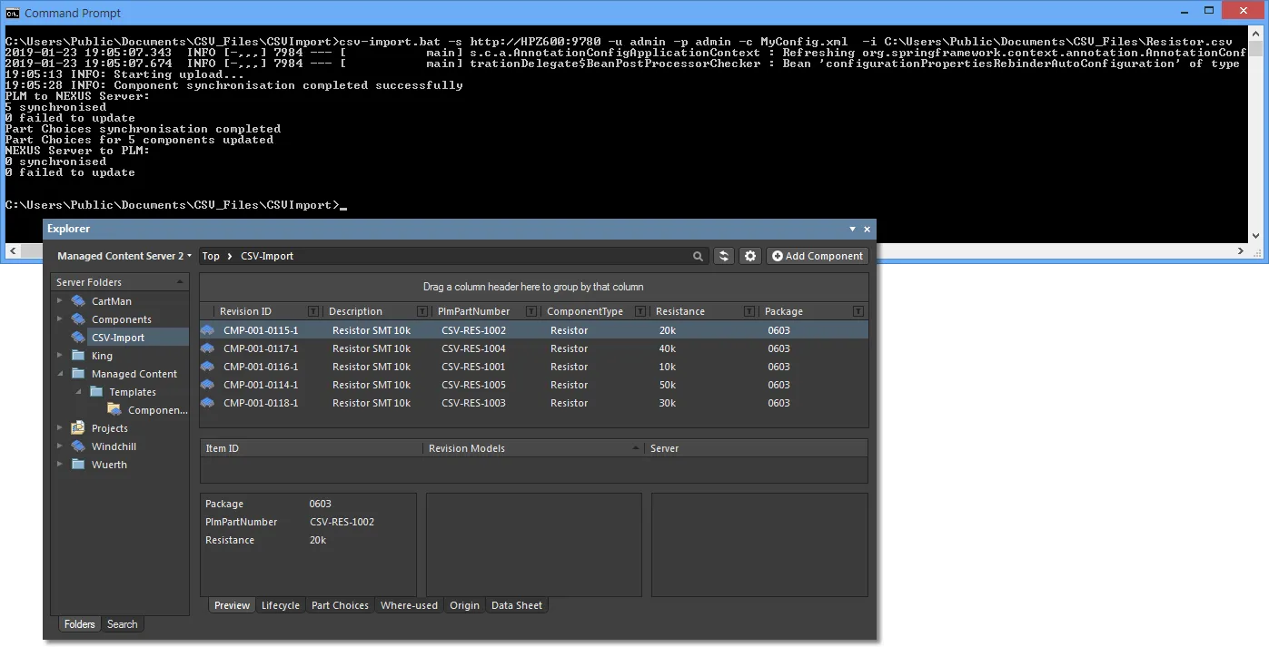
If the component entries already exist in the Server (as imported in the above
Auto mode example process), new Revisions will be created and the remapped parameters added to the existing data – existing parameters are not removed.
Additional features:
- An applied configuration file determines all settings for the import process, including parameter mappings, independently of related server Templates.
- All parameters may be mapped to accommodate the input CSV file parameters, including what name is used in the file for PLM Number and the part manufacturer data.
- Multiple Entity definitions, including their constituent parameter Attributes, can be included in a configuration file. Copy an existing Entity group entry, say for
Resistor, and then paste/edit this to create another for Capacitor.
- When a source path is specified without a CSV file, the tool will search the source folder for CSV filenames that match Entity definitions in the configuration file. So if configuration Entity references exist for
Capacitor and Resistor and matching CSV files are found, the data for those components will be imported into the server. This is effectively the tool's batch operation mode.
- If the source CSV file uses a particular filename structure that does not match the standard server Component Types (
Resistor, Capacitor, etc), this can be allowed for by mapping the PLM class in the configuration file. For example if the source file is PLM-Export_Resistors.csv, the PLM class entry plmType=”Resistor” can be changed to plmType=”PLM-Export_Resistors”.
Direct System Support
Altium Concord Pro provides direct support for the following enterprise systems:
- PTC Windchill® PLM (11.0 M030)
- Arena® PLM
- Oracle® Agile™ PLM
Due to API limitations, library synchronization with Manufacturer Part/Part Choices is not yet supported when working with an integrated Windchill instance.
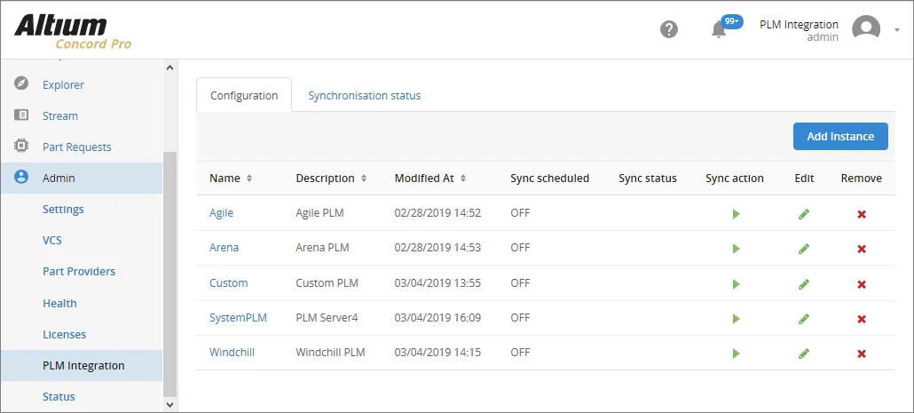
Connecting to Your Enterprise System
Connection to your enterprise system is performed from the Admin - PLM Integration page of Concord Pro's browser interface. This involves uploading the applicable XML-based configuration file and enabling/configuring synchronization of the components in your enterprise system, with those in the Concord Pro server.
To create a new interface instance, click the

button. As many instances can be defined as required, to interface your Concord Pro server to various different enterprise systems. For example, your components might reside in a particular instance and another division may be using a different instance (of the same or differing enterprise system). Each instance must be uniquely named and have a configuration file.
Sample configuration files are provided as part of the installation – click on the section below for more information:
Sample Configuration Files
Sample configuration files are provided with the Concord Pro installation – click the Download sample configuration link (under the Configuration tab) to obtain the zip file ConfigurationSamples.zip. This archive contains basic configuration files for Windchill, Arena and Agile systems:
- dm-Agile-config-basic.xml
- dm-Windchill-config-basic.xml
- dm-Arena-config-basic.xml
 Sample configuration files are provided for use as part of the Concord Pro installation.
Modify these to suit your company's enterprise system instance and requirements.
The configuration files contain detailed comments to help guide you in what to configure, and how.
Upload a suitable configuration file for the new enterprise system instance from the  button, then use the
  button to check for warning and errors that relate to the new configuration. The test process will first request sign in credentials for the new enterprise system instance if these have not been already established via the
  button.
When the connection validation report is run, the server analyses the current configuration settings for compatibility with both Concord Pro data and the target enterprise system data. Configuration issues such as path errors, unmatched component type definitions and parameters, invalid Lifecycle or Revision settings are detected and reported in the Configuration Validation Report dialog.
 Add and configure the interface to your company's enterprise system then check and correct any errors in the uploaded Configuration file.
While it's most likely you will need to set up only one enterprise system instance, any number of instances may be added to the Concord Pro server.
When a configuration file has been edited and then re-uploaded to the enterprise system instance, make sure that you use the
option to detect any problems that may have been introduced.
Component Synchronization
Synchronization of components between Concord Pro and the connected enterprise system instance – or to be more specific, their parametric data – involves the following:
- Configuring the synchronization for each component type. This involves:
- Determining the direction of synchronization.
- Determining which components are involved, and where components are to be created.
- Configuring parameter mapping.
- Performing the synchronization.
The first of the above items is handled in the configuration file used for the connected enterprise system instance. The synchronization itself can be performed on-demand from the PLM Integration page of the Concord Pro server's browser interface, and/or can be scheduled. The latter is automated synchronization at periodic intervals, which is defined when configuring or editing the connection to the enterprise system instance.
Configuring Synchronization
Within the configuration file, you define a section for synchronization mapping for each dedicated part type. On the Concord Pro side, this is the component of type altiumType (and is the name you see in Altium Designer's Component Type dialog). On the enterprise system side, a part is created of type plmType. This is declared as an Entity in the file, an example of which might be, for capacitors:
<Entity altiumType="Capacitor" plmType="Capacitor">
.
.
</Entity>
The plmType value may vary, depending on the particular enterprise system instance you are using.
Within the Entity tags, two sections are used to control and configure synchronization from the Concord Pro server to the enterprise system instance, and the enterprise system instance to the Concord Pro server – allowing for uni- or bi-directional synchronization. Use the following sections, in conjunction with the comments available in the sample configuration files, to learn more. Ultimately, what gets defined in the configuration file will vary depending on your specific needs.
ToPlm
This section is used to control and configure synchronization from the Concord Pro server to the enterprise system instance in the form:
<ToPlm sync="true">
.
.
<\ToPlm>
To disable synchronization in this direction, set sync="false".
Within the ToPlm section, the following sections are defined:
- How new components are created in the enterprise system instance – between the tagset <CreateInfo> and </CreateInfo>.
- Filtering to limit which components in Concord Pro are synchronized with the enterprise system - between the tagset <SourceCriteria> and </SourceCriteria>.
This is essential if you have 6000 capacitors for example in your Concord Pro server, but only want a folder of 85 ceramic capacitors to be synchronized! You could specify a particular folder be involved (e.g. with the entry: <Folder>Components/Capacitors/Ceramic</Folder>). You can optionally use other criteria to narrow the filter even more, based on parameter values – all such criteria filters should be joined by AND.
- A listing of attributes (parameters) that should be passed for the components from Concord Pro to the enterprise system – between the tagset <Attributes> and </Attributes>. An example of this is:
<Attributes>
<!-- Value has to be provided as attribute is annotated as required -->
<ns2:Attribute required="true">
<ns2:Key>Name</ns2:Key>
<ns2:Value>${parameter.Name}</ns2:Value>
</ns2:Attribute>
<ns2:Attribute attributeType="item" primaryKeyOrdinal="1" required="true">
<ns2:Key>Number</ns2:Key>
<ns2:Value>${parameter.PlmPartNumber}</ns2:Value>
</ns2:Attribute>
<!-- Concord Pro component description will go to enterprise system field Description. Value will be prefixed with 'Extended' -->
<ns2:Attribute attributeType="revision" required="true">
<ns2:Key>Description</ns2:Key>
<ns2:Value>Extended ${parameter.Description}</ns2:Value>
</ns2:Attribute>
</Attributes>
Notice that the part number that gets created on the enterprise system side (PlmPartNumber) is the primary key for linking the components on either side, and will be propagated back to the component in Concord Pro. Notice also, that there is the notion of Item parameters (attributeType="item"). These parameters, such as the PlmPartNumber parameter above, are added to the parent Component Item in Concord Pro and available to its revisions. They do not cause a new revision of a Component Item to be created if their value is changed. This is in contrast with Revision parameters (attributeType="revision"). These parameters, such as the Description parameter above, cause a new revision of a Component Item to be created if their value is changed.
ToAltium
This section is used to control and configure synchronization from the enterprise system instance to the Concord Pro server in the form:
<ToAltium sync="true">
.
.
<\ToAltium>
To disable synchronization in this direction, set sync="false".
Within the ToAltium section, the following sections are defined:
- How and where new components are created in Concord Pro - between the tagset <CreateInfo> and </CreateInfo>.
If a component already exists, it will be updated, and not moved. The component template and Item naming scheme are taken from the nominated Server folder. In the sample configurations, a default revision naming scheme (1-Level Revision Scheme) and lifecycle definition (Component Lifecycle) are defined to be used. If a component template is defined for the target folder, the schemes defined there will be used instead.
- Filtering of data retrieved from the enterprise system instance – between the tagset <SourceCriteria> and </SourceCriteria>.
- A listing of attributes (parameters) that should be passed for the components from the enterprise system to the Concord Pro server – between the tagset <Attributes> and </Attributes>. An example of this is:
<Attributes>
<!-- Name field from enterprise system will be passed to name/comment field in Concord Pro -->
<ns2:Attribute attributeType="revision">
<ns2:Key>name</ns2:Key>
<ns2:Value>${attribute.Name}</ns2:Value>
</ns2:Attribute>
<!-- Description field from enterprise system will be passed to Description field in Concord Pro on revision level -->
<!-- Revision level attributes will cause new revision to be created in case parameter value is changed -->
<ns2:Attribute attributeType="revision" required="true">
<ns2:Key>Description</ns2:Key>
<ns2:Value>${attribute.Description}</ns2:Value>
</ns2:Attribute>
<!-- Number field from enterprise system will be passed to PlmPartNumber field in Concord Pro on item level -->
<!-- Item level parameters will not cause revision update when changed -->
<ns2:Attribute attributeType="item" primaryKeyOrdinal="1" required="true">
<ns2:Key>PlmPartNumber</ns2:Key>
<ns2:Value>${attribute.Number}</ns2:Value>
</ns2:Attribute>
</Attributes>
Notice that the part number on the enterprise system side (PlmPartNumber) is the primary key for linking the components on either side, and is propagated back to the Concord Pro component. Notice also, that there is the notion of Item parameters (attributeType="item"). These parameters, such as the PlmPartNumber parameter above, are added to the parent Component Item in the Concord Pro server, and available to its revisions. They do not cause a new revision of a Component Item to be created if their value is changed. This is in contrast with Revision parameters (attributeType="revision"). These parameters, such as the Description parameter above, cause a new revision of a Component Item to be created if their value is changed.
- Component Part Choices can be propagated from the enterprise system to Concord Pro using the Key entries MFR_NAME and
MFR_PART_NUMBER. The (enterprise system) Value entry in the Attribute set will be as specified on the enterprise system side. An example entry in the configuration file's ToAltium section might be:
<ns2:Attribute attributeType="revision" required="false">
<ns2:Key>MFR_NAME</ns2:Key>
<ns2:Value>${attribute.ManufacturerName}</ns2:Value>
</ns2:Attribute>
Performing Component Synchronization
Synchronization itself is performed from the PLM Integration page of Concord Pro's browser interface. Click the  control associated with the enterprise system instance that you wish to synchronize. The synchronization process will proceed in accordance with the settings defined in the associated configuration file.
Synchronization will involve only those components that have been modified since the last synchronization was run (i.e. their timestamp is later than the last synchronization date), and which pass the synchronization criteria in the configuration file. This is referred to as Incremental Synchronization.
 Component synchronization in progress between Concord Pro and the indicated enterprise system instance.
The control changes to  . If you want to stop the synchronization process, click this control. A confirmation window will appear, click
  to stop the synchronization – all components already synchronized will remain so, but no further synchronization beyond that point will occur.
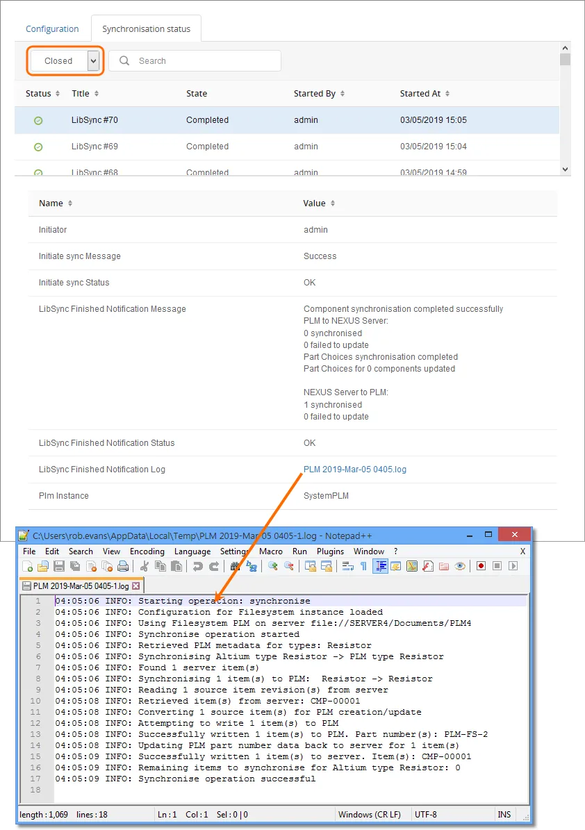
Refresh the browser (F5) to check when the synchronization process is complete. To see further details on the completed process, or to confirm its success or otherwise, select the Synchronisation status tab and choose the Closed listing option – if a process is still running it will show in the Active listing. Details of the selected synchronization event are shown in the lower pane, which also includes a link to the system log file (PLM [date-number].log) for the event.
Scheduled Component Synchronization
You also have the ability to schedule automated synchronization. To do so, edit the enterprise system instance (from the main PLM Integration page, click on its name, or the associated  control), select the Component Synchronisation tab and enable the Synchronize PLM Components with server on schedule option. Use the Synchronize every controls to set up the automated sync schedule as required. The system is very flexible and allows you to:
- Set up scheduled synchronization every 15/30/45/60/75/90 minutes.
- Set up scheduled synchronization every x hours.
- Set up scheduled daily synchronization, to be performed at a nominated time.
The schedule you define will be reflected back on the main PLM Integration page, in the Sync scheduled column.
 Setting up a synchronization schedule.
To set up scheduled synchronization requires you to provide valid credentials (for your enterprise system). Click the

button and enter your
User name and
Password into the subsequent
PLM Credentials window. Without valid credentials, scheduled synchronization will remain in the OFF state. On-demand synchronization will also not be possible.
You can also run the synchronization process on-demand in the Edit instance page. Click the  button and choose which mode of sync you need:
- Incremental – in this mode, only those components that have been modified since the last synchronization was run (i.e. their timestamp is later than the last synchronization date), and that pass the synchronization criteria in the configuration file, will be included in the sync, with changes propagated accordingly. This is the default mode, and is the same mode that is run by clicking the control for an enterprise system instance on the main PLM Integration page.
- Full – this mode forces a full synchronization. All components that pass the synchronization criteria in the configuration file will be included in the sync, with changes propagated accordingly.
