
Configuring PCB Board Region Object Properties in Altium NEXUS
Parent page: Board Region
PCB Editor object properties are definable options that specify the visual style, content and behavior of the placed object. The property settings for each type of object are defined in the following way.
- Post-placement settings – all Board Region object properties are available for editing in the Board Region dialog and the Properties panel when a placed Board Region is selected in the design space.

Actions
These controls are used to add or remove the coverlay from the current Board Region. To enable the Add and Remove Coverlay buttons, the Board Region must have a Layer Stack assigned that has the Is Flex option enabled and has Coverlay layers included in its set of layers.
- Add Coverlay - Add auto-created coverlay polygons to the selected Board Region.
- Remove Coverlay - Remove auto-created and manually defined coverlay polygons from the selected Board Region.
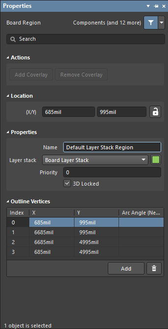
Location
- (X/Y) - the X and Y location coordinates of the first vertex placed when the Board Region was created, relative to the current design space origin. Edit to change the X or Y position of the Board Region. Values can be entered in either metric or imperial; include the units when entering a value whose units are not the current default.
Properties
- Name - user-definable name of this Board Region. Naming each Board Region is helpful when there are multiple regions in the design.
- Layer Stack - specifies which Layer Stack is assigned to this Board Region. The drop-down list will include all Layer Stacks (substacks) defined in the Layer Stack Manager.
- Color - click to open a color palette to set/change the color of the selected Board Region(s). Note that color changes are applied to all board regions that share the Layer stack used by the selected Board Region.
- Priority - the Priority value is used to determine which Board Region is rendered last. Use this when designing a board with a flex region within a board cutout in a rigid region - the flex region must have a higher Priority value than the surrounding rigid region (and the board cutout must trace around the flex-within-cutout region).
- 3D Locked - check this box to fix this Board Region when folding the board in 3D view mode. Only one rigid Board Region can be locked.
Outline Vertices
This region is used to modify the individual vertices of the currently selected Board Region object. You can modify the locations of existing vertices, add new vertices or remove them as required. Arc connections between vertex points can be defined and support is also provided for exporting vertex information to and importing from a CSV-formatted file (via the right-click menu).
- Vertices Grid - lists all of the vertex points currently defined for the Board Region in terms of:
- Index - the assigned index of the vertex (non-editable).
- X - the X (horizontal) coordinate for the vertex. Click to edit.
- Y - the Y (vertical) coordinate for the vertex. Click to edit.
- Arc Angle (Neg = CW) - the angle of an arc that is drawn to connect this vertex point to the next. By default, connections are straight-line edges with this field remaining blank. Click to edit then enter an arc angle as required. Entry of a positive value will result in an arc drawn counterclockwise. To draw a clockwise arc, enter a negative value.
- Add - click to add a new vertex point. The new vertex will be added below the currently focused vertex entry and will initially have the same X,Y coordinates as the focused entry. Click the
 to remove the currently selected vertex.