
Configuring PCB Design View Object Properties in Altium NEXUS
Created: 四月 19, 2022 | Updated: 四月 19, 2022
| Applies to version: 4
This document is no longer available beyond version 4. Information can now be found here: Design View Properties for version 5
Parent page: Design View
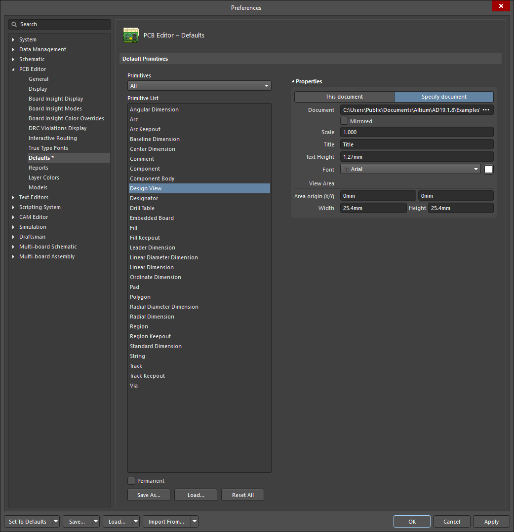
PCB Editor object properties are definable options that specify the visual style, content and behavior of the placed object. The property settings for each type of object are defined in two different ways:
- Pre-placement settings – most Design View object properties, or those that can logically be pre-defined, are available as editable default settings on the PCB Editor - Defaults page of the Preferences dialog (accessed by using the
 button at the top-right of the design space). Select the object in the Primitive List to reveal its options on the right.
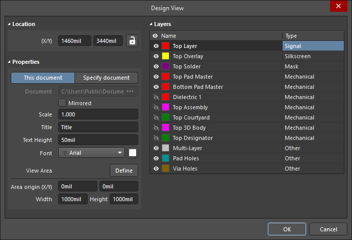
- Post-placement settings – all Design View object properties are available for editing in the Design View dialog and the Properties panel when a placed Design View is selected in the design space.
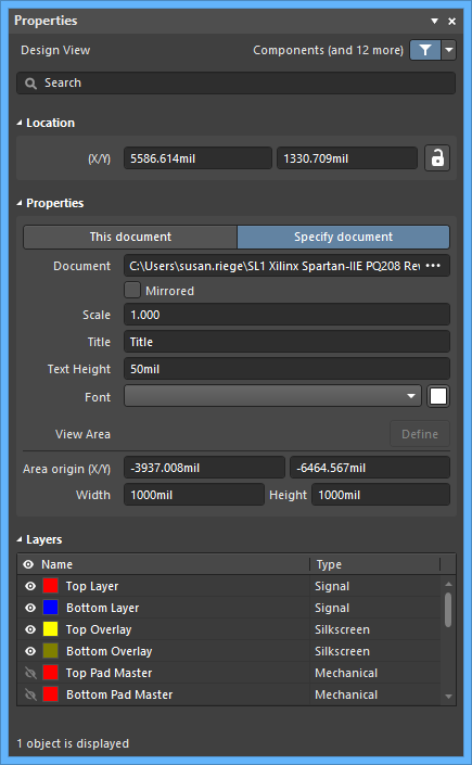
Location (Properties panel only)
- (X/Y) - the current X and Y locations of the Design View reference point.
Properties
- This document - select to specify the properties for the currently active document.
- Specify document - select to specify the properties for a different document. When selected, click
 in the Document field then browse for the desired document.
 - Document - click to search for and select the desired document when Specify document is selected.
- Mirrored - click to enable a flipped (mirrored) image of the board area in the Design View.
- Scale - click to define the object size as a multiplying factor.
- Title - enter the title of the Design View.
- Text Height - enter the Design View's title text height.
- Font - use the drop-down to select the desired font for the title. Use the color box to open a color chooser for the title text. Note that the color must contrast the design space background color for visibility.
- Define - click to return to the design space with a cross-hair cursor then use click-drag to define the rectangular region of the view.
Layers (Properties panel only)
This region provides a list of all board layers that can be configured to show specific layers in the Design View.
- Name - the name of the layer. Use the
 or
or  icon to show or hide (respectively) the listed layer in the Design View.
 - Type - the layer type.