
Dimension
The Home | Dimension region in the PCB or PCB Footprint Library editor allows you to add dimensioning to a PCB design or footprint, respectively.

Angular Dimension Object

An angular dimension is a group design object. It allows for the dimensioning of angular distances.
Angular dimension objects are available for placement in the PCB or PCB Footprint Library editor by choosing Home | Dimension | Dimension then selecting Angular from the drop-down list.
After launching the command, the cursor will change to a cross-hair and you will enter dimension placement mode. Placement is made by performing the following sequence of actions:
- Position the cursor over the first reference object then click or press Enter to anchor the first dimension reference (the inside reference).
- Move the cursor to the next required position associated with the first object being dimensioned then click or press Enter to anchor the second dimension reference (the outside reference).
- Position the cursor over the second reference object then click or press Enter to anchor the third dimension reference (the inside reference).
- Move the cursor to the next required position associated with the second object being dimensioned then click or press Enter to anchor the fourth dimension reference (the outside reference).
- Place the dimension text for the angle as desired then click or press Enter to complete placement.
- Continue placing further angular dimensions, or right-click or press Esc to exit placement mode.
Additional actions that can be performed during placement are:
- Press the + and - keys (on the numeric keypad) to cycle forward and backward through all visible layers in the design to change placement layer quickly.
Graphical Editing
This method of editing allows you to select a placed angular dimension object directly in the workspace and change properties such as the position of its text and its reference points graphically.
When an angular dimension object is selected, the following editing handles are available:

- Click & drag A or B to change the position of the dimension text and extension line length.
- Click & drag C and E to detach the dimension from the first reference object.
- Click & drag D and F to detach the dimension from the second reference object.
If the angular dimension object is totally non-referenced (i.e. it is not attached to any reference design objects) click anywhere on it away from editing handles and drag to reposition it. While dragging, the angular dimension can be rotated or mirrored:
- Press the Spacebar to rotate the angular dimension counterclockwise or Shift+Spacebar for clockwise rotation. Rotation is in accordance with the value for the Rotation Step defined on the PCB Editor – General page of the Preferences dialog.
- Press the X or Y keys to mirror the angular dimension along the X-axis or Y-axis respectively.
Non-Graphical Editing
The Inspector panel enables you to interrogate and edit the properties of one or more design objects in the active document. Used in conjunction with appropriate filtering, the panel can be used to make changes to multiple objects of the same kind, from one convenient location.
Notes
- An angular dimension object can be moved in the following ways:
- Selecting both the dimension object and the objects that are being dimensioned. The whole can be dragged to a new location as required.
- Selecting an object that is being dimensioned only. The dimension text will follow the object in its alignment plane only. The dimension extensions will expand/contract to keep the relationship between dimension and object being dimensioned.
- Selecting the dimension object only. It is important to note that the dimension cannot be moved on its own if it is referenced by a design object. To move the dimension only, it must first be detached from the objects it is dimensioning.
- The dimension's value automatically updates as its start or endpoints are moved. Likewise, if the position of an object that a reference point of the dimension is anchored to is changed, the dimension will update and expand/contract to reflect this.
- When the reference or references to which a dimension object is attached are deleted, a dialog will open asking whether the dimension should also be deleted. If the dimension is not deleted, it remains in the workspace, but non-referenced.
Baseline Dimension Object

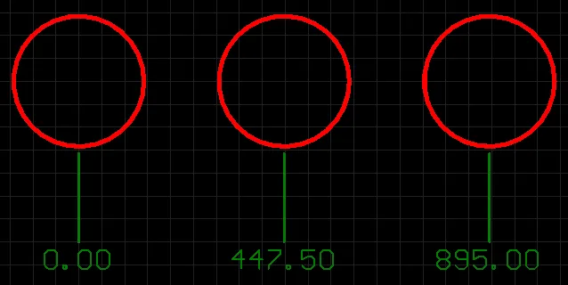
A baseline dimension is a group design object. It allows for the dimensioning of a linear distance of a collection of references, relative to a single base reference. The first point chosen is the 'base'. All subsequent points are relative to this first point. The dimension value in each case is, therefore, the distance between each reference point and the 'base', measured in the default units. The references may be objects (tracks, arcs, pads, vias, text, fills, polygons, or components) or points in free space.
Baseline dimension objects are available for placement in the PCB or PCB Footprint Library editor by choosing Home | Dimension | Dimension then selecting Baseline from the drop-down list.
After launching the command, the cursor will change to a cross-hair and you will enter dimension placement mode. Placement is made by performing the following sequence of actions:
- Position the cursor then click or press Enter to anchor the dimension start point (this is the first reference point or 'base').
- Move the cursor to the required endpoint then click or press Enter to anchor the dimension endpoint (this is the second reference point).
- The text can now be initially positioned. Click or press Enter when the text is in the desired position to effect placement.
- Move the cursor to subsequent reference points then click or press Enter twice to effect placement (first click to anchor to a reference and second click after positioning the text).
- When all required references in the baseline dimension have been covered, right-click or press Esc to exit placement mode.
Additional actions that can be performed during placement are:
- Press the + and - keys (on the numeric keypad) to cycle forward and backward through all visible layers in the design to change placement layer quickly.
- Press Spacebar to rotate the dimension counterclockwise or Shift+Spacebar for clockwise rotation. Rotation is in accordance with the value for the Rotation Step defined on the PCB Editor – General page of the Preferences dialog.
- While attributes can be modified during placement (Tab to bring up the associated Inspector panel), keep in mind that these will become the default settings for further placement.
Graphical Editing
This method of editing allows you to select a placed baseline dimension object directly in the workspace and change properties such as the position of its text and its reference points graphically.
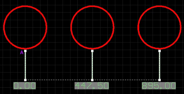
When a baseline dimension object is selected, the following editing handles are available:

- Click & drag the handles at arrows to adjust the dimension text position parallel to the extensions.
- Click & drag A to move the base point of the dimension.
- Click & drag subsequent handles to move each reference individually with respect to the base.
If the baseline dimension object is totally non-referenced (i.e. it is not attached to any reference design objects) click anywhere on it away from editing handles and drag to reposition it. While dragging, the baseline dimension can be rotated (Spacebar/Shift+Spacebar) or mirrored (X or Y keys to mirror along the X-axis or Y-axis respectively).
Non-Graphical Editing
The Inspector panel enables you to interrogate and edit the properties of one or more design objects in the active document. Used in conjunction with appropriate filtering, the panel can be used to make changes to multiple objects of the same kind, from one convenient location.
Notes
- A baseline dimension object can be moved in the following ways:
- Selecting both the dimension object and the objects that are being dimensioned. The whole can be dragged to a new location as required.
- Selecting an object that is being dimensioned only. The dimension text will follow the object in its alignment plane only. The dimension extensions will expand/contract to keep the relationship between dimension and object being dimensioned.
- Selecting the dimension object only. It is important to note that the dimension cannot be moved on its own if it is referenced by a design object. To move the dimension only, it must first be detached from the objects it is dimensioning.
- The dimension's value automatically updates as its start or endpoints are moved. Likewise, if the position of an object that a reference point of the dimension is anchored to is changed, the dimension will update and expand/contract to reflect this.
- When the reference or references to which a dimension object is attached are deleted, a dialog will open asking whether the dimension should also be deleted. If the dimension is not deleted, it remains in the workspace, but non-referenced.
Center Dimension Object

A center dimension is a group design object. It allows for the center of an arc or circle to be marked.
Center dimension objects are available for placement in the PCB or PCB Footprint Library editor by choosing Home | Dimension | Dimension then selecting Center from the drop-down list.
After launching the command, the cursor will change to a cross-hair and you will enter dimension placement mode. Placement is made by performing the following sequence of actions:
- Position the cursor then click or press Enter to anchor the dimension to the desired arc or circle.
- Move the dimension until the desired sizing is achieved then click or press Enter to complete placement.
- Continue placing further center dimensions, or right-click or press Esc to exit placement mode.
Additional actions that can be performed during placement are:
- Press the + and - keys (on the numeric keypad) to cycle forward and backward through all visible layers in the design to change placement layer quickly.
- Press Spacebar to rotate the dimension counterclockwise or Shift+Spacebar for clockwise rotation. Rotation is in accordance with the value for the Rotation Step defined on the PCB Editor – General page of the Preferences dialog.
- Press the Tab key to access an associated Inspector panel, from where properties for the dimension can be changed on the fly.
Graphical Editing
This method of editing allows you to select a placed center dimension object directly in the workspace and change its size and orientation graphically.
When a center dimension object is selected, the following editing handles are available:

- Click & drag A to change the size of the dimension. As you drag a handle, the dimension can be rotated (Spacebar/Shift+Spacebar).
Non-Graphical Editing
The Inspector panel enables you to interrogate and edit the properties of one or more design objects in the active document. Used in conjunction with appropriate filtering, the panel can be used to make changes to multiple objects of the same kind, from one convenient location.
Notes
- A center dimension object can be moved in the following ways:
- Selecting both the dimension object and the circle/arc that is being dimensioned. The whole can be dragged to a new location as required.
- Selecting the circle/arc that is being dimensioned only. The dimension will move with the object.
- When the reference arc or circle to which a center dimension object is attached is deleted, a dialog will open asking whether the dimension should also be deleted. If the dimension is not deleted, it remains in the workspace, but non-referenced. Note, however, that a non-referenced center dimension cannot be attached to another circle/arc.
Datum Dimension Object
A datum dimension is a group design object. It allows for the dimensioning of a linear distance of a collection of objects, relative to a single reference object. The first object chosen is the 'base'. All subsequent objects are relative to this first object. The dimension value in each case is, therefore, the distance between each reference object and the 'base', measured in the default units. The references may be tracks, arcs, pads, vias, text, fills, polygons, or components.
Datum dimension objects are available for placement in the PCB or PCB Footprint Library editor by choosing Home | Dimension | Dimension then selecting Datum from the drop-down list.
After launching the command, the cursor will change to a cross-hair and you will enter dimension placement mode. Placement is made by performing the following sequence of actions:
- Position the cursor then click or press Enter to anchor the dimension start point (this is the first reference object or 'base').
- Move the cursor to the next required object then click or press Enter to anchor the dimension endpoint (this is the second reference object).
- Move the cursor to subsequent reference objects then click or press Enter. When all desired objects have been selected, right-click or press Esc.
- The text can now be initially positioned. Click or press Enter when the text is in the desired position to complete placement and exit placement mode.
Additional actions that can be performed during placement are:
- Press the + and - keys (on the numeric keypad) to cycle forward and backward through all visible layers in the design, respectively, to change placement layer quickly.
- Press Spacebar to rotate the dimension counterclockwise or Shift+Spacebar for clockwise rotation. Rotation is in accordance with the value for the Rotation Step defined on the PCB Editor – General page of the Preferences dialog.
- Press the Tab key to access an associated Inspector panel, from where properties for the dimension can be changed on-the-fly.
Graphical Editing
This method of editing allows you to select a placed datum dimension object directly in the workspace and change properties such as the position of its text and its reference points graphically.
When a datum dimension object is selected, the following editing handles are available:
- Click & drag any of the handles at the text end of the extensions to adjust the dimension text position for all cases simultaneously.
- Click & drag A to move the base point of the dimension.
- Click & drag subsequent handles to move each reference individually, with respect to the base.
If the datum dimension object is totally non-referenced (i.e. it is not attached to any reference design objects) click anywhere on it – away from editing handles – and drag to reposition it. While dragging, the datum dimension can be rotated (Spacebar/Shift+Spacebar) or mirrored (X or Y keys to mirror along the X-axis or Y-axis respectively).
Non-Graphical Editing
The Inspector panel enables you to interrogate and edit the properties of one or more design objects in the active document. Used in conjunction with appropriate filtering, the panel can be used to make changes to multiple objects of the same kind, from one convenient location.
Notes
- A datum dimension object can be moved in the following ways:
- Selecting both the dimension object and the objects that are being dimensioned. The whole can be dragged to a new location as required.
- Selecting an object that is being dimensioned only. The dimension text will follow the object in its alignment plane only. The dimension extensions will expand/contract to keep the relationship between dimension and object being dimensioned.
- Selecting the dimension object only. It is important to note that the dimension cannot be moved on its own if it is referenced by a design object. To move the dimension only, it must first be detached from the objects it is dimensioning.
- The dimension's value automatically updates as its start or endpoints are moved. Likewise, if the position of an object that a reference point of the dimension is anchored to is changed, the dimension will update and expand/contract to reflect this.
- When the reference or references to which a dimension object is attached are deleted, a dialog will open asking whether the dimension should also be deleted. If the dimension is not deleted, it remains in the workspace, but non-referenced.
Leader Dimension Object

A leader dimension is a group design object. It allows for the labeling of an object, point or area. The label text can be encapsulated in a circle, a square, or not at all, while the pointer can be an arrow or a dot.
Leader dimension objects are available for placement in the PCB or PCB Footprint Library editor by choosing Home | Dimension | Dimension then selecting Leader from the drop-down list.
After launching the command, the cursor will change to a cross-hair and you will enter dimension placement mode. Placement is made by performing the following sequence of actions:
- Position the cursor then click or press Enter to anchor the dimension start point (this is the location of the arrowhead or dot).
- Move the cursor then click or press Enter to anchor a series of vertex points that define the shape of the leader.
- After placing the final required vertex point, right-click or press Esc to effect placement of the text label and exit placement mode.
Additional actions that can be performed during placement are:
- Press the + and - keys (on the numeric keypad) to cycle forward and backward through all visible layers in the design, respectively, to change placement layer quickly.
- Press the Tab key to access an associated Inspector panel, from where properties for the dimension can be changed on-the-fly.
Graphical Editing
This method of editing allows you to select a placed leader dimension object directly in the workspace and change properties such as the position of its text, its shape and its reference point graphically.
When a leader dimension object is selected, the following editing handles are available:

- Click & drag A to move the start point of the dimension (i.e. the position of the arrowhead).
- Click & drag B to move the endpoint of the dimension (i.e. the position of the text label).
- Click & drag intermediate handles to change the shape of the leader.
If the leader dimension object is totally non-referenced (i.e. it is not attached to a reference design object) click anywhere on it – away from editing handles – and drag to reposition it. While dragging, the leader dimension can be rotated or mirrored:
- Press the Spacebar to rotate the leader dimension counterclockwise or Shift+Spacebar for clockwise rotation. Rotation is in accordance with the value for the Rotation Step defined on the PCB Editor – General page of the Preferences dialog.
- Press the X or Y keys to mirror the leader dimension along the X-axis or Y-axis respectively.
Non-Graphical Editing
The Inspector panel enables you to interrogate and edit the properties of one or more design objects in the active document. Used in conjunction with appropriate filtering, the panel can be used to make changes to multiple objects of the same kind, from one convenient location.
Notes
- A leader dimension object can be moved in the following ways:
- Selecting both the dimension object and the object that is being dimensioned. The whole can be dragged to a new location as required.
- Selecting the object that is being dimensioned only. The dimension will follow the object. The segment of the leader dimension – between the arrow/dot and the first defined elbow – will expand/contract to keep the relationship between dimension and object dimensioned.
- Selecting the dimension object only. It is important to note that the dimension cannot be moved on its own if it is referenced by a design object. To move the dimension only, it must first be detached from the object it is dimensioning.
- When the reference to which a dimension object is attached is deleted, a dialog will open asking whether the dimension should also be deleted. If the dimension is not deleted, it remains in the workspace, but non-referenced.
Linear Diameter Dimension Object

A linear diameter dimension is a group design object. It allows for the dimensioning of an arc or circle with respect to the diameter rather than the radius. The dimension can be placed either internally or externally.
Linear Diameter dimension objects are available for placement in the PCB or PCB Footprint Library editor by choosing Home | Dimension | Dimension then selecting Linear Diameter from the drop-down list.
After launching the command, the cursor will change to a cross-hair and you will enter dimension placement mode. Placement is made by performing the following sequence of actions:
- Position the cursor then click or press Enter to anchor the dimension to the desired arc or circle. The position of the dimension is determined by the alignment angle for the dimension.
- Move the dimension text to the desired position (either internal or external) then click or press Enter to complete placement.
- Continue placing further linear diameter dimensions, or right-click or press Esc to exit placement mode.
Additional actions that can be performed during placement are:
- Press the + and - keys (on the numeric keypad) to cycle forward and backward through all visible layers in the design, respectively, to change placement layer quickly.
- Press Spacebar to rotate the dimension counterclockwise or Shift+Spacebar for clockwise rotation. Rotation is in accordance with the value for the Rotation Step defined on the PCB Editor – General page of the Preferences dialog.
- Press the Tab key to access an associated Inspector panel, from where properties for the dimension can be changed on-the-fly.
Graphical Editing
This method of editing allows you to select a placed linear diameter dimension object directly in the workspace and change properties such as the position of its text and its reference points graphically.
When a linear diameter dimension object is selected, the following editing handles are available:

- Click & drag A or B to adjust the dimension text position parallel to the extensions.
- Click & drag C or D to detach the dimension from the reference object.
If the linear diameter dimension object is totally non-referenced (i.e. it is not attached to a reference design object) click anywhere on it – away from editing handles – and drag to reposition it. While dragging, the linear diameter dimension can be rotated (Spacebar/Shift+Spacebar).
Non-Graphical Editing
The Inspector panel enables you to interrogate and edit the properties of one or more design objects in the active document. Used in conjunction with appropriate filtering, the panel can be used to make changes to multiple objects of the same kind, from one convenient location.
Notes
- A linear diameter dimension object can be moved in the following ways:
- Selecting both the dimension object and the object that is being dimensioned. The whole can be dragged to a new location as required.
- Selecting the object that is being dimensioned only. The dimension text will follow the object in its alignment plane only. The dimension extensions will expand/contract to keep the relationship between dimension and object dimensioned.
- Selecting the dimension object only. It is important to note that the dimension cannot be moved on its own if it is referenced by a design object. To move the dimension only, it must first be detached from the object it is dimensioning.
- The dimension's value automatically updates as the diameter of the reference arc or circle changes.
- When the reference arc or circle to which a linear diameter dimension object is attached is deleted, a dialog will open asking whether the dimension should also be deleted. If the dimension is not deleted, it remains in the workspace but non-referenced.
Linear Dimension Object

A linear dimension is a group design object. It places dimensioning information on the current PCB layer with respect to a linear distance. The dimension value is the distance between the start and end markers (reference points selected by the user) measured in the default units. The references may be objects (tracks, arcs, pads, vias, text, fills, polygons, or components) or points in free space.
Linear dimension objects are available for placement in the PCB or PCB Footprint Library editor by choosing Home | Dimension | Dimension then selecting Linear from the drop-down list.
After launching the command, the cursor will change to a cross-hair and you will enter dimension placement mode. Placement is made by performing the following sequence of actions:
- Position the cursor then click or press Enter to anchor the dimension start point (this is the first reference point).
- Move the cursor then click or press Enter to anchor the dimension endpoint (this is the second reference point).
- The text can now be initially positioned. Move the cursor then click or press Enter when the text is in the desired position to complete dimension placement.
- Continue placing further linear dimensions, or right-click or press Esc to exit placement mode.
Additional actions that can be performed during placement are:
- Press the + and - keys (on the numeric keypad) to cycle forward and backward through all visible layers in the design, respectively, to change placement layer quickly.
- Press Spacebar to rotate the dimension counterclockwise or Shift+Spacebar for clockwise rotation. Rotation is in accordance with the value for the Rotation Step defined on the PCB Editor – General page of the Preferences dialog.
- Press the Tab key to access an associated Inspector panel, from where properties for the dimension can be changed on-the-fly.
Graphical Editing
This method of editing allows you to select a placed linear dimension object directly in the workspace and change properties such as the position of its text and its reference points graphically.
When a linear dimension object is selected, the following editing handles are available:

- Click & drag A or B to adjust the dimension text position and extension line length.
- Click & drag C or D to move the start or end reference points of the dimension.
If the linear dimension object is totally non-referenced (i.e. it is not attached to any reference design objects) click anywhere on it – away from editing handles – and drag to reposition it. While dragging, the linear dimension can be rotated (Spacebar/Shift+Spacebar) or mirrored (X or Y keys to mirror along the X-axis or Y-axis respectively).
Non-Graphical Editing
The Inspector panel enables you to interrogate and edit the properties of one or more design objects in the active document. Used in conjunction with appropriate filtering, the panel can be used to make changes to multiple objects of the same kind, from one convenient location.
Notes
- A linear dimension object can be moved in the following ways:
- Selecting both the dimension object and the object that is being dimensioned. The whole can be dragged to a new location as required.
- Selecting the object that is being dimensioned only. The dimension text will follow the object in its alignment plane only. The dimension extensions will expand/contract to keep the relationship between dimension and object being dimensioned.
- Selecting the dimension object only. It is important to note that the dimension cannot be moved on its own if it is referenced by a design object. To move the dimension only, it must first be detached from the objects it is dimensioning.
- The dimension's value automatically updates as its start or endpoints are moved. Likewise, if the position of the object that either reference point of the dimension is anchored to is changed, the dimension will update and expand/contract to reflect this.
- When the reference or references to which a dimension object is attached are deleted, a dialog will open asking whether the dimension should also be deleted. If the dimension is not deleted, it remains in the workspace, but non-referenced.
Radial Diameter Dimension Object

A radial diameter dimension is a group design object. It allows for the dimensioning of an arc or circle with respect to the diameter rather than the radius. The dimension can be placed either internally or externally in relation to the circumference of the arc/circle.
Radial Diameter dimension objects are available for placement in the PCB or PCB Footprint Library editor by choosing Home | Dimension | Dimension then selecting Radial Diameter from the drop-down list.
After launching the command, the cursor will change to a cross-hair and you will enter dimension placement mode. Placement is made by performing the following sequence of actions:
- Position the cursor then click or press Enter to anchor the dimension to the desired arc or circle.
- Move the dimension's arrow pointer to the desired location around the arc or circle. The arrow can be placed either inside or outside and movement is in accordance with the Angular Step value in the Inspector panel. When the required position has been attained, click or press Enter to lock the arrow in place.
- The text can now be initially positioned in relation to the tail of the arrow pointer. Move the text into the required position then click or press Enter to complete placement.
- Continue placing further radial diameter dimensions, or right-click or press Esc to exit placement mode.
Additional actions that can be performed during placement are:
- Press the + and - keys (on the numeric keypad) to cycle forward and backward through all visible layers in the design, respectively, to change placement layer quickly.
- Press the Tab key to access an associated Inspector panel, from where properties for the dimension can be changed on-the-fly.
Graphical Editing
This method of editing allows you to select a placed radial diameter dimension object directly in the workspace and change properties such as the position of its text and its reference point graphically.
When a radial diameter dimension object is selected, the following editing handles are available:

- Click & drag A to adjust the leader position, relative to the 'tail' of the arrow pointer.
- Click & drag B to adjust the position of the arrow pointer around the circumference of the circle or arc or change the length of the arrow leader line.
- Click & drag C to move the start point of the dimension.
If the radial diameter dimension object is totally non-referenced (i.e. it is not attached to a reference design object) click anywhere on it – away from editing handles – and drag to reposition it. While dragging, the radial diameter dimension can be rotated or mirrored:
- Press the Spacebar to rotate the radial diameter dimension counterclockwise or Shift+Spacebar for clockwise rotation. Rotation is in accordance with the value for the Rotation Step defined on the PCB Editor – General page of the Preferences dialog.
- Press the X or Y keys to mirror the radial diameter dimension along the X-axis or Y-axis respectively.
Non-Graphical Editing
The Inspector panel enables you to interrogate and edit the properties of one or more design objects in the active document. Used in conjunction with appropriate filtering, the panel can be used to make changes to multiple objects of the same kind, from one convenient location.
Notes
- A radial diameter dimension object can be moved in the following ways:
- Selecting both the dimension object and the object that is being dimensioned. The whole can be dragged to a new location as required.
- Selecting the object that is being dimensioned only. The dimension text will follow the object in its alignment plane only. The dimension pointer and tail will expand/contract to keep the relationship between dimension and object being dimensioned.
- Selecting the dimension object only. It is important to note that the dimension cannot be moved on its own if it is referenced by a design object. To move the dimension only, it must first be detached from the object it is dimensioning.
- The dimension's value automatically updates as the radius of the reference arc or circle changes.
- When the reference arc or circle to which a radial diameter dimension object is attached is deleted, a dialog will open asking whether the dimension should also be deleted. If the dimension is not deleted, it remains in the workspace, but non-referenced.
Radial Dimension Object

A radial dimension is a group design object. It allows for the dimensioning of a radius with respect to an arc or circle. The dimension can be placed either internally or externally in relation to the circumference of the arc/circle.
Radial dimension objects are available for placement in the PCB or PCB Footprint Library editor by choosing Home | Dimension | Dimension then selecting Radial from the drop-down list.
After launching the command, the cursor will change to a cross-hair and you will enter dimension placement mode. Placement is made by performing the following sequence of actions:
- Position the cursor then click or press Enter to anchor the dimension to the desired arc or circle.
- Move the dimension's arrow pointer to the desired location around the arc or circle. The arrow can be placed either inside or outside and movement is in accordance with the Angular Step value in the Inspector panel. When the required position has been attained, click or press Enter to lock the arrow in place.
- The text can now be initially positioned in relation to the tail of the arrow pointer. Move the text into the required position then click or press Enter to complete placement.
- Continue placing further radial dimensions, or right-click or press Esc to exit dimension placement mode.
Additional actions that can be performed during placement are:
- Press the + and - keys (on the numeric keypad) to cycle forward and backward through all visible layers in the design, respectively, to change placement layer quickly.
- Press the Tab key to access an associated Inspector panel, from where properties for the dimension can be changed on-the-fly.
Graphical Editing
This method of editing allows you to select a placed radial dimension object directly in the workspace and change properties such as the position of its text, the location of its arrow pointer and its reference point graphically.
When a radial dimension object is selected, the following editing handles are available:

- Click & drag A to adjust the dimension text position, relative to the 'tail' of the arrow pointer.
- Click & drag B to adjust the position of the arrow pointer around the circumference of the circle or arc.
- Click & drag C to move the start point of the dimension.
If the radial dimension object is totally non-referenced (i.e. it is not attached to a reference design object) click anywhere on it – away from editing handles – and drag to reposition it. While dragging, the radial dimension can be rotated or mirrored:
- Press the Spacebar to rotate the radial dimension counterclockwise or Shift+Spacebar for clockwise rotation. Rotation is in accordance with the value for the Rotation Step defined on the PCB Editor – General page of the Preferences dialog.
- Press the X or Y keys to mirror the radial dimension along the X-axis or Y-axis respectively.
Non-Graphical Editing
The Inspector panel enables you to interrogate and edit the properties of one or more design objects in the active document. Used in conjunction with appropriate filtering, the panel can be used to make changes to multiple objects of the same kind, from one convenient location.
Notes
- A radial dimension object can be moved in the following ways:
- Selecting both the dimension object and the object that is being dimensioned. The whole can be dragged to a new location as required.
- Selecting the object that is being dimensioned only. The dimension text will follow the object in its alignment plane only. The dimension pointer and tail will expand/contract to keep the relationship between dimension and object being dimensioned.
- Selecting the dimension object only. It is important to note that the dimension cannot be moved on its own if it is referenced by a design object. To move the dimension only, it must first be detached from the object it is dimensioning.
- The dimension's value automatically updates as the radius of the reference arc or circle changes.
- When the reference arc or circle to which a radial dimension object is attached is deleted, a dialog will open asking whether the dimension should also be deleted. If the dimension is not deleted, it remains in the workspace, but non-referenced.
Dimension Object Properties
All properties of a dimension object are available for editing in the Inspector panel when a placed dimension object is selected in the design space.


Style
- Width - the current dimension line width.
Extension Line
- Width - the current width for the dimension extension lines.
- Gap - the distance between a dimension extension line and the object being dimensioned.
- Offset - the current arrow line offset with respect to the dimension extension line.
-
Text Gap - the current gap to the left and right of the dimension value text.
- Leader Shape - use the drop-down to determine which shape is used to encapsulate the dimension text. Available options are Automatic, Round, and Square. If Round or Square are selected, enter the desired Size.
- Arrow Style - use the drop-down to select the desired leader style. Choices are Arrow or Dot. Enter the desired Size.
Arrow Style
- Arrow Size - the current arrowhead size. The size is measured as the distance between the arrow tip and the end of the arrow 'legs'.
- Arrow Length - the current arrow length. Note that the value entered into this field is applied only when the Arrow Position (in the Properties region) is set to Outside.
Properties
- Text - enter the desired text.
- Layer - the layer to which the dimension is currently assigned. Dimensions can be assigned to any available layer. Use the drop-down to select a different layer.
- Text Position - the current position of the dimension text. Use the associated drop-down list to choose one of the following options:
- Automatic - the dimension text will be placed in the most appropriate location with respect to the dimension so that the text itself is always readable.
- Aligned - Center - the dimension text will be aligned to the center of the dimension line.
- Aligned - Top - the dimension text will be aligned above the dimension line and centered.
- Aligned - Bottom - the dimension text will be aligned below the dimension line and centered.
- Aligned - Right - the dimension text will be aligned to the right of the dimension line (outside of the extension line).
- Aligned - Left - the dimension text will be aligned to the left of the dimension line (outside of the extension line). For a Leader Dimension, the dimension text will be aligned with the angle of the last 'leg' of the leader line.
- Aligned - Inside Right - the dimension text will be aligned to the right of the dimension line (inside the extension line).
- Aligned - Inside Left - the dimension text will be aligned to the left of the dimension line (inside the extension line).
- Unidirectional - the dimension text will be aligned to the center of the dimension line but will remain horizontal regardless of the dimension alignment angle. For a Leader Dimension, the dimension text will remain horizontal regardless of the dimension alignment angle.
- Manual - the dimension text will be available for manual placement directly in the design space.
- Arrow Position - the current position of the dimension arrows. The available options are:
- Inside - arrows will be positioned inside the dimension's extension lines (pointing outwards).
- Outside - arrows will be positioned outside the dimension's extension lines (pointing inwards).
- Angular Step - the current angular step setting for the dimension. This is the rotation step used when placing the arrow portion of the dimension. Moving the arrow around the circle or arc during placement of the dimension, the number and position of possible places to anchor the dimension are determined by this angular step value.
- Text Height - the current height of the dimension text characters. The character width used to display or print the text is automatically proportioned to this height. A minimum height of 36mil (0.9mm) will allow the text to be legibly photo-plotted.
- Rotation - the angle of alignment of the dimension, measured counterclockwise in degrees from the horizontal.
- Size - the current length of the center dimension's crosshair lines (or the diameter of the encompassing circle).
Font Type
- TrueType - use this field to choose the required TrueType font. The drop-down list is populated with TrueType and OpenType (a superset of TrueType) fonts found in the \Windows\Fonts folder. Note that the list will include only entries for detected (and uniquely named) root fonts. Use the B (bold) and I (Italic) options to add emphasis to the text.
- Stroke
- Font - use this field to choose the required Stroke font. Available options are:
- Default - a simple vector font that supports pen plotting and vector photo-plotting.
- Serif - more complex font that will slow down vector output generation, such as Gerber.
- Sans Serif - a more complex font that will slow down vector output generation, such as Gerber.
- Font - use this field to choose the required Stroke font. Available options are:
- Stroke Width - displays the current stroke width.
Units
-
Primary Units - the current unit that is selected for the calculation and display of the dimension value. Choose either Mils, Millimeters, Inches, Centimeters, or Automatic.
- Value Precision - the current setting for the number of decimal places to the right of the decimal point for which the dimension will be displayed.
Value
- Format - the current setting for the format of the dimension text. Use the associated drop-down to change the format as required. The options listed will depend on the chosen Unit and present based on the actual value for the current dimension. In generic terms, the available options are:
- None - no dimension text is displayed.
- Value Only - no units are displayed, only the dimension value (e.g., 600.00).
- Value and Unit - units are displayed after the dimension value (e.g., 600.00mil).
- Value and Bracketed Unit - units are displayed in brackets after the dimension value (e.g., 600.00(mil)).
- Prefix - the current prefix of the dimension value.
- Suffix - the current suffix of the dimension value.
- Sample - this field presents a sample of how the dimension text will appear in accordance with the specified Format and any defined Prefix and/or Suffix.