
Creating the Physical Multi-board Assembly
Altium Designer supports creating a multiple-board assembly, referred to as a multi-board assembly. Once the logical structure of the system is defined in a multi-board schematic (*.MbsDoc), the physical multi-board design is then created by transferring the system design into an empty multi-board assembly document (*.MbaDoc). This process will load the physical representation (PCBs and other multi-board assemblies) referenced by each logical block in the multi-board schematic into the multi-board assembly editor. This page discusses that process.
To learn more about the logical design stage of a multi-board assembly, refer to the page Capturing the Logical System Design.
To create a new multi-board assembly document:
-
Add a new multi-board assembly document (
*.MbaDoc) to the multi-board project by right-clicking the project entry in the Projects panel and then selecting Add New to Project » Multi-board Assembly from the context menu. -
Save the new multi-board assembly document (right-click its entry in the Projects panel and select Save As from the context menu).
-
Transfer the logical representation of the system from the multi-board schematic to the multi-board assembly document – learn more.
-
If the enclosure is available, load it into the assembly – learn more.
-
Position each element within the assembly – refer to the Positioning & Orienting Your Boards page to learn more.
-
Connect elements within the assembly using mates – refer to the Working with Mates page to learn more.

An example multi-board assembly. Multiple connected PCBs are placed within an enclosure.

Transferring the System Design to the Multi-board Assembly Document
The multi-board design is transferred from the multi-board schematic to the multi-board assembly document using either of the following commands:
-
Design » Update Assembly - <MultiBoardAssemblyDocumentName>.MbaDoc from the multi-board schematic editor's main menus.
-
Design » Import Changes From <MultiBoardProjectName>.PrjMbd from the multi-board assembly editor's main menus.
When you run one of these commands, the software interrogates each module on the multi-board schematic, identifies the PCB/assembly that has been selected for each of the child projects, and presents the list of modifications required to add each of those boards to the assembly in the Engineering Change Order dialog.

The board from each PCB project is listed as an ECO modification and is loaded into the multi-board Assembly editor when the ECOs are executed.
When the ![]() button is clicked, the boards/assemblies are loaded into the multi-board assembly editor. Each board/assembly is placed in the design space in the same orientation that it has in the child project. This process will take some time, as the full dataset for each PCB must be analyzed and loaded.
button is clicked, the boards/assemblies are loaded into the multi-board assembly editor. Each board/assembly is placed in the design space in the same orientation that it has in the child project. This process will take some time, as the full dataset for each PCB must be analyzed and loaded.

Boards in this multi-board assembly loaded into the multi-board assembly editor design space, ready to be positioned.
Adding Additional Objects to the Multi-board Assembly
You also can load additional objects into a multi-board assembly (as well as the PCBs referenced in the multi-board schematic). Additional objects can be loaded using the Design menu or by using the buttons located at the top of the Multi-board Assembly panel.

Use the appropriate command or button to:
-
Insert PCB Part (
 ) – insert another PCB into this assembly.
-
Insert MBA Part (
 ) – insert another multi-board assembly into this assembly.
-
Insert STEP Part (
 ) – insert a STEP format mechanical model into this assembly.
Updating or Editing an Assembly Part
Locking/Unlocking a Part
To lock/unlock a part, select the desired part, right-click, and then choose the Lock Selected Part/Unlock Selected Part command in the context menu to lock/unlock the part (or mated parts) at its current location in the assembly editor design space. Alternatively, right-click on a part entry in the Multiboard Assembly panel, then choose Locked.
-
A locked part cannot be edited/moved.
-
Parts that are locked are marked with a padlock icon in the Multiboard Assembly panel.
-
A locked individual part does not display an object gizmo (to learn more about the object gizmo, refer to the Positioning & Orienting Your Boards page).
-
A locked part cannot be mated if it is selected as the source (the object that moves – to learn more about the mating the parts, refer to the Working with Mates page).
Updating a Part
If a part or 3D body added into an assembly has been updated, the update can be loaded into the multi-board assembly using one of the following actions:
-
Choose the Edit » Update All Parts command from the main menus or right-click anywhere in the design space and choose the Update All Parts command from the context menu (shortcut:
Shift+Ctrl+U) to update all parts in the active multi-board assembly with the latest layout information from their corresponding child PCB documents. -
Select the required part(s) and choose the Edit » Update Selected Part command from the main menus or right-click anywhere in the design space and choose the Update Selected Part command from the context menu (shortcut:
Ctrl+U) to update the selected parts in the active multi-board assembly with the latest layout information from their corresponding child PCB documents. -
Select the required 3D body and choose the Edit » Update Selected 3D Body command from the main menus or right-click anywhere in the design space and choose the Update Selected 3D Body command from the context menu to update the selected 3D bodies in the active multi-board assembly with the latest layout information from their corresponding child PCB documents.
Editing a Part
An assembly or PCB edit session can be launched from within the multi-board assembly editor. Select the required part and run the Edit » Edit Selected Part command or right-click anywhere in the design space and choose the Edit Selected Part command from the context menu (shortcut: Ctrl+E). After launching the command, you will enter part editing mode, with the selected PCB zoomed and centered (where possible) to fit within the main design window. The board will remain displayed in its full coloring, with all other boards grayed-out (read-only).
Make changes to the placement of components as required, using manual placement and/or alignment features. Once you are finished editing, use the Finish Part Editing command (Ctrl+E). The view of the design space will return to fit all boards in the assembly, with the board that was being edited remaining selected.
If you want to cancel editing without implementing any of the changes, use the Cancel Part Editing command.
Navigating and Managing the Multi-board Assembly
To navigate and manage a multi-board assembly, you can use the Multiboard Assembly panel.

The panel presents an expandable tree view of the complete assembly structure, including:
-
The included boards (PCBs) and multi-board assemblies and the components, layers and nets within each PCB
-
STEP models that have been included
-
Other multi-board assemblies that have been included
-
Mates formed between objects in the assembly
Highlighting Elements in the Multi-board Assembly
The Multiboard Assembly panel provides highlighting capabilities, where the part selected in the tree is highlighted in the design space. The highlighting is bi-directional for selections made at the top of the assembly tree, for example, the selection state of panel entries will change in response to top-level objects that have been selected in the design space. From the panel, selection is supported at all levels of the tree where it is logical. For example, selecting an individual net will highlight that net throughout the board, but selecting an individual dielectric layer will not highlight that layer. The standard Windows Shift+Click or Ctrl+Click shortcuts can be used to multi-select in the panel.

Three boards selected in the design space are also highlighted in the panel.
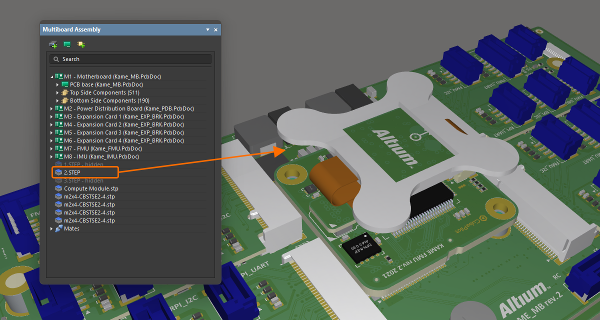
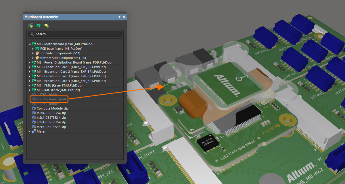
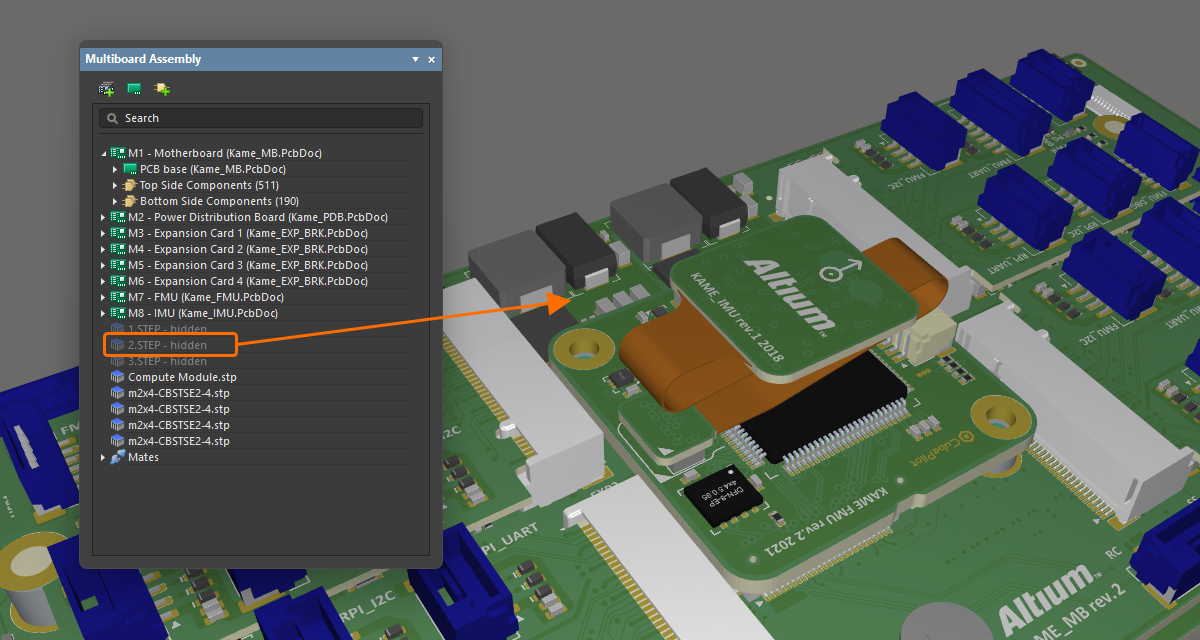
Controlling the Visibility and Transparency of Assembly Parts
As well as highlighting a specific part or parts, the panel can also be used to control the visibility and transparency of the parts currently selected in the panel. Right-click the selected part(s) then choose Visible or Transparent from the context menu. Transparent parts will become see-through. Parts with their Visible option disabled will be hidden.
|
A STEP model is fully visible in the assembly. The same model was made transpatent. The same model was completely hidden. |
Measuring the Distance
The Tools » Measure Distance command from the main menus (shortcut: Ctrl+M) is used to measure distances between 3D bodies in the multi-board assembly. After launching the command, you will enter measurement mode. Measurement is performed as follows:
-
Choose the first 3D object, or specific face of that object. As you move the cursor over a potential 3D object, the color of that object will change color. If you want to select a specific face of the object, hold the
Ctrlkey as you move the cursor – the face currently under the cursor will be highlighted. With the cursor in place, click to confirm object/face selection. -
Choose the second 3D object, or specific face of that object.
-
The tool visually presents the shortest distance between the two chosen objects (faces).
-
Continue measuring the distance between other objects/faces or press
Escto exit measurement mode.
Collision Testing
Collisions are flagged whenever two objects have surfaces that touch or intersect.
To check for collisions, select Tools » Check Collisions (shortcut: Ctrl+K). After launching the command, the software checks for collisions between the various entities involved in the multi-board assembly. First, each board is checked for collision with the upper and lower enclosure/case parts (STEP parts), followed by checking between the boards themselves (PCBs).
Any collisions will be reported through the Messages panel, and the offending objects highlighted using the Violation system color. Use the Details region of the Messages panel to investigate which component on a board involved in a conflict is causing the collision.
If required, collision violations highlighted in the design space after having run collision checking can be cleared by selecting the Tools » Clear Violations command.
Support for Rigid-Flex
The multi-board assembly editor supports rigid-flex PCBs. Rigid-flex is the name given to a printed circuit that is a combination of both flexible circuit(s) and rigid circuit(s). The multi-board assembly editor displays the PCB in the final folded state as defined in the PCB editor.

For information about designing rigid-flex PCBs, refer to the Designing a Rigid-Flex PCB page.
Exporting to MCAD
The assembly can be exported in STEP 3D or Parasolid format. To export the entire assembly in STEP 3D (*.step or *.stp), select File » Export » STEP 3D from the main menus. To export the entire assembly in Parasolid format (*.x_t), select File » Export » Parasolid from the main menus.

An example of the STEP file of the multi-board assembly opened in an MCAD tool.
Exporting to PDF 3D
A multi-board assembly document can also be exported to a PDF file (*.pdf). To do this, choose the File » Export to PDF File command from the main menus.

For more information, refer to the Preparing a PDF3D File page.