
Changing Your View of the Design Space
When you first transfer the boards into the multi-board assembly editor, they are neatly placed on the same plane – you can imagine them as all being laid out next to each other on a virtual table. Within a few minutes, you will have moved this one, rotated that one, and pulled another one closer to you! And then you will have rotated the view, now you are not even sure which way is up!
Working in a 3D design space requires skill in managing your view into that space, and skill in manipulating the objects within that space. These are separate skills, controlling your view of the space and positioning the boards within that space – let's start with the techniques you use to control your view of the space.
 ).
).Orienting Your View in the Design Space
On the bottom left of the multi-board assembly editor design space is a red/green/blue axis marker, this is referred to as the design space gizmo.
 to control your view of the design space.")
Use the design space gizmos (colored arrows and planes at the bottom left of the design space) to control your view of the design space.
The design space gizmo is used to change the orientation of your view into the design space.
Each design space axis, and its corresponding plane, is assigned a color:
-
Blue – Z axis, viewing into the XY plane. You can think of this as the top or bottom view.
-
Red – X axis, viewing into the YZ plane. You can think of this as the front or rear view.
-
Green – Y axis, viewing into the XZ plane. You can think of this as the left or right view.
As you hover the mouse over a colored gizmo element, it will become lighter, indicating that it is active. When you click on that color, the view will reorient so that you are looking down that axis into the assembly. A second click will flip the view over, looking down the same axis from the other direction. The table below gives more details about the various behaviors.
View Control Shortcuts that Align to the Design Space Axes
These shortcuts align the view to the design space axes:
| Shortcut | Behavior |
|---|---|
Z key, or click Blue on the design space gizmo |
Re-orient the view to be looking down the Z axis, directly into the XY plane. Click Blue a second time to view from the opposite direction or use the Shift+Z shortcut. |
X key, or click Red on the design space gizmo |
Re-orient the view to be looking down the X axis, directly into the YZ plane. Click Red a second time to view from the opposite direction or use the Shift+X shortcut. |
Y key, or click Green on the design space gizmo |
Re-orient the view to be looking down the Y axis, directly into the XZ plane. Click Green a second time to view from the opposite direction or use the Shift+Y shortcut. |
Use the design space gizmo to change the orientation of your view.
View Control Shortcuts that Align with the Current View
Many of the view movements you can perform are not referenced from the design space axes, instead, they are referenced to your current view. Your current view is referred to as the current view plane, it is the plane you are currently seeing looking into your monitor. For example, when you zoom in the design space contents are bought closer to you, regardless of the current angle of the design space axes.
These shortcuts are relative to your current view plane:
| Shortcut | Behavior |
|---|---|
Ctrl+Mouse Wheel |
Zoom in/out |
Right-Click, Hold&Drag |
Displays the panning hand cursor as you slide the view of the design space around, in the current view plane. |
Shift+Right-Click, Hold&Drag |
Rotate the view of the design space around the current horizontal and vertical view plane axes. The click-and-drag location defines the center of rotation. |
Ctrl+PgDn |
Zoom the view to fit all objects, including the origin marker. |
Your current view can be changed using mouse and keyboard shortcuts.
Changing the Projection Type
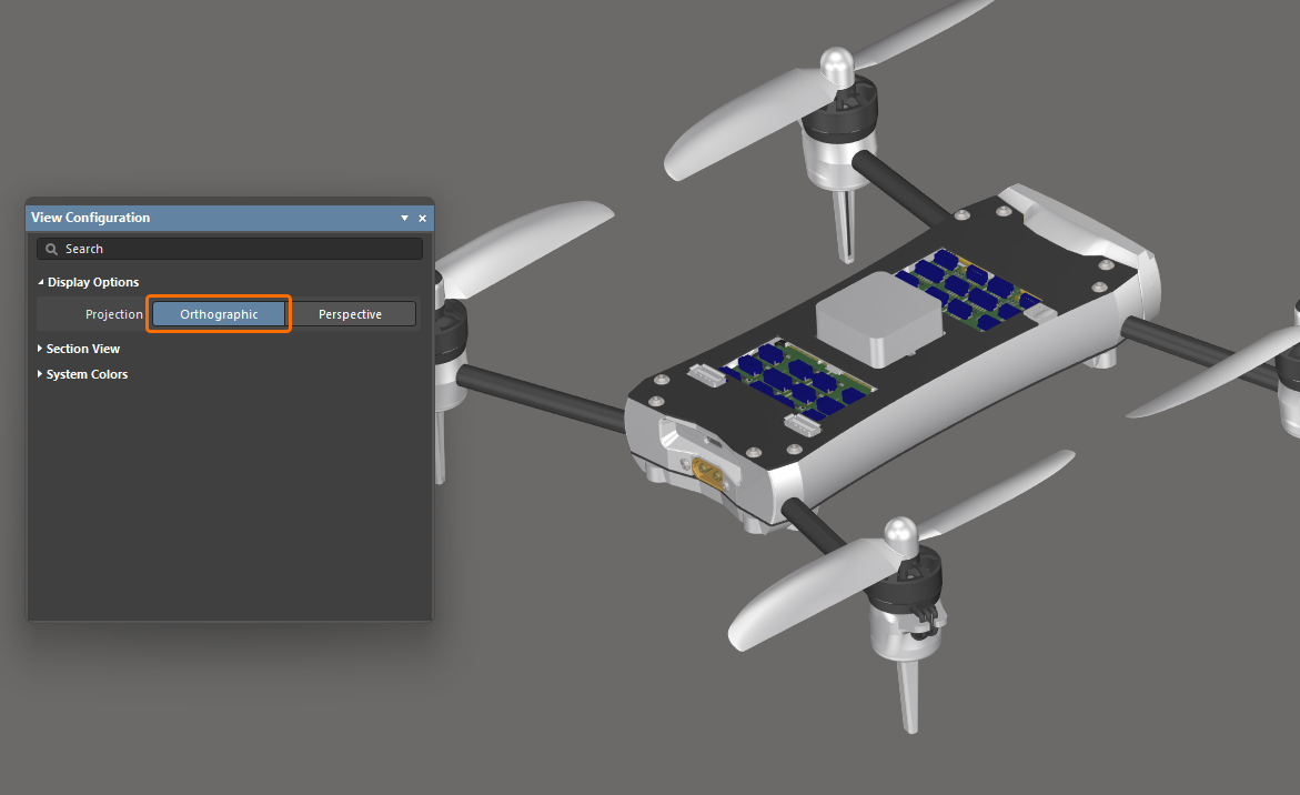
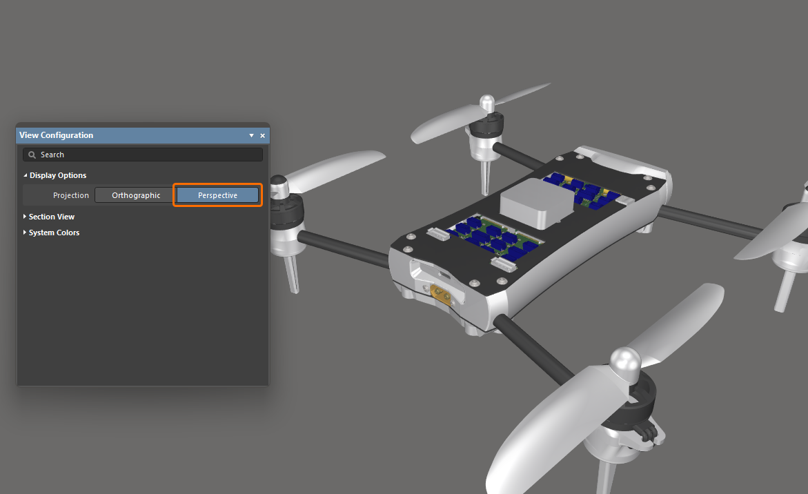
You can change the view of the multi-board assembly editor to perspective or orthographic by toggling the View » Toggle Projection Type command from the main menus (shortcut: P) or by using the Projection option in the Display Options region of the View Configuration panel.
-
Perspective is a view of a three-dimensional image that portrays height, width, and depth for a more realistic image or graphic.
-
Orthographic is a view of three-dimensional objects that are created by projecting a view of an object onto a plane which is usually positioned so that it is parallel to one of the planes of the object. Choose this option to see the exact position of objects and text on the multi-board assembly without being obscured by surrounding objects.
|
The Projection of a multi-board assembly is set to Orthographic. The Projection of the same multi-board assembly is set to Perspective. |
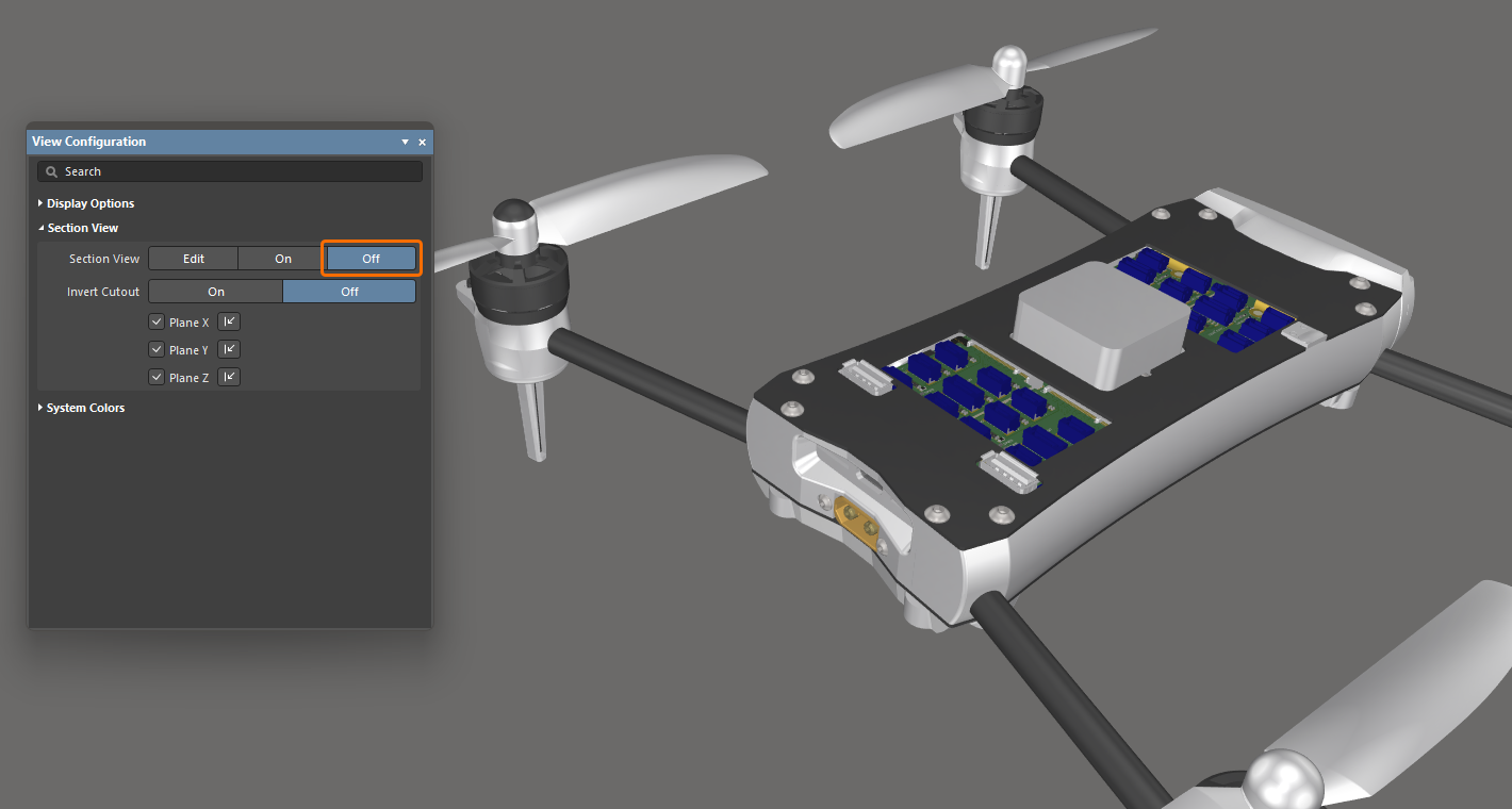
Defining a Section View of the Assembly
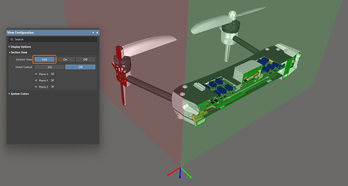
A section view is one that can be used to reveal detail within an assembly that might normally not be visible. This is achieved by defining planes where a section of the assembly is sliced or cut away. The multi-board assembly editor supports defining a section plane along each of the three axes, allowing the section definition to be in 1, 2, or 3 directions.
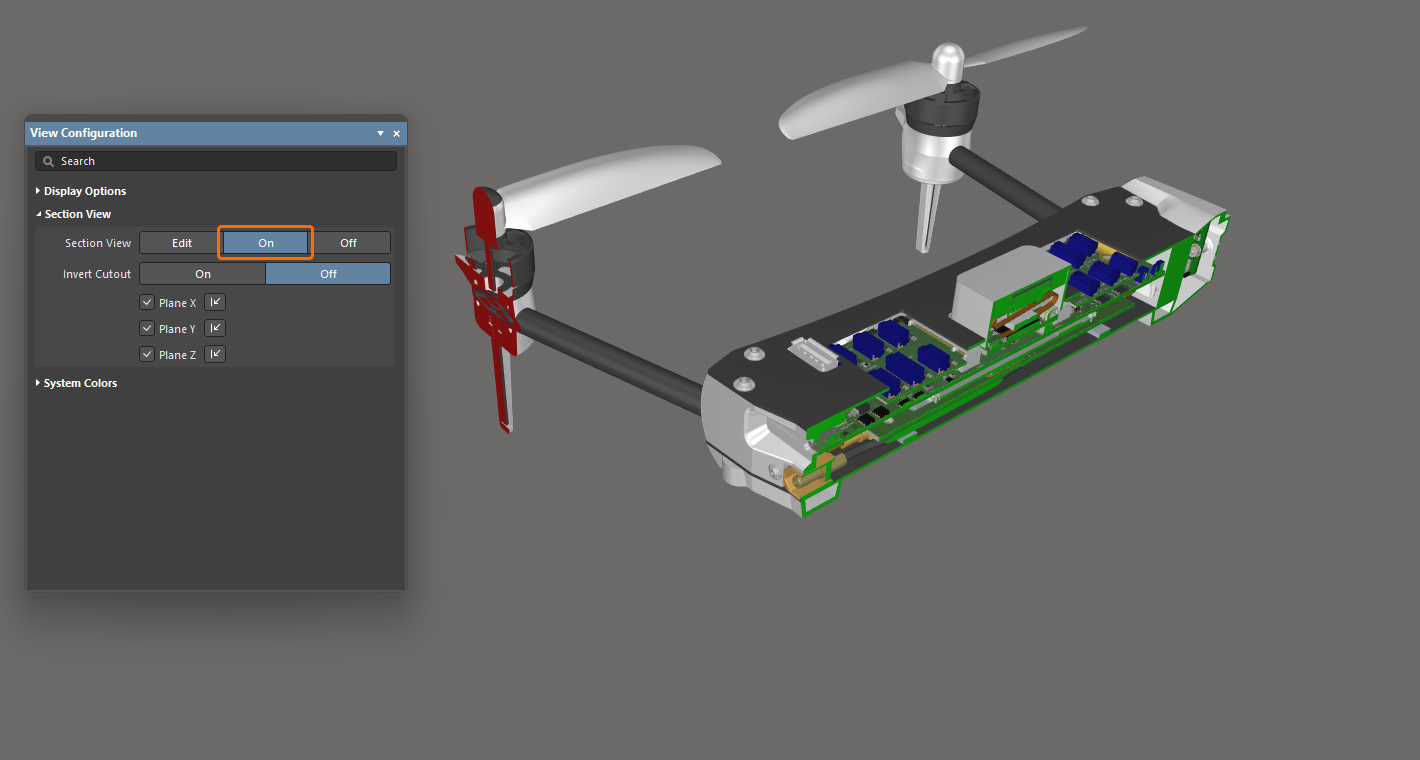
The section view can be Off, On, or in Edit mode. In Edit mode, the section planes are displayed; each plane is indicated by a colored semi-transparent surface radiating away from the section view origin. The section view origin is defined by the three colored arrows, referred to as the section view gizmo. You can enable their display and configure their direction in the View Configuration panel in the Section View region.
|
Enable Edit mode to have sectioning applied and to make planes visible and editable. Enable On mode to have sectioning applied and planes hidden. Enable Off mode to hide panels and to give a clearer view of the multi-board assembly. |
To work with the section view:
-
Toggle the display of the Section View between Edit/On/Off by choosing View » Toggle Section View from the main menus (shortcut:
Shift+Ctrl+V). -
In Edit mode, the location of each section plane can be changed by clicking and dragging on the appropriate colored arrow of the section view gizmo.
-
The section view is controlled by a section view gizmo, which controls the location of the X, Y, and Z section planes. The location of the gizmo defines the origin of the section view.
-
The default is to hide everything that is in the current section view's negative space, i.e., display only objects that appear in the section view's positive space. This behavior is flipped if the Invert Cutout option is enabled in the View Configuration panel. Then the objects within the negative space are displayed and the objects within the positive space are hidden.
-
In Edit mode, a specific section plane can be enabled/disabled using the Plane X / Plane Y / Plane Z checkboxes (one or two planes can be disabled) and the direction that the sectioning is applied can be switched for each plane using the relevant
 control. The settings will be kept when switching to the section view's On mode.
Configuring System Colors
Use the System Colors region of the View Configuration panel to configure colors of system elements, such as selected objects, design space background, etc. Click a color swatch to select the required color for the corresponding element.
