The software includes a number of validation checks, which can be included as an output, during output generation. Each produces an HTML report file.
Validation outputs can be added to the active Output Job file from the menu of the [Add New Validation Output] control in the Validation Outputs region of the file or from the Edit » Add Validation Outputs sub-menus of the main menus.

Note that the setup for these validation reports is held in the OutputJob. When you configure a validation check elsewhere in the software the settings are held with that file - for example, the settings for project error checking are stored in the project file, PCB DRC settings are stored in the PCB file.
Using validation reports defined in an assigned Output Job file provides the ability to validate your designs as an integral part of its
design project release process. These validation checks will be performed on every release and the release will fail if any validation checks are not passed successfully. This gives you additional peace of mind that costly errors do not creep in to your released designs due to last minute changes. Validation is run at the
Validate Design stage of the process flow within the PCB Release view. In Design Mode, the validation checks are performed directly on your project, before outputs are generated. In Release Mode, the release flow first builds a self-contained snapshot from your project that includes all project documents and external dependencies, and the validation checks are performed on this snapshot. This provides additional security that the snapshot has correctly captured all the required dependencies for your project.
Validating Component Status
Workspace Components offer the designer a formal collection of high-quality, high-integrity, design building blocks. Revision-controlled and lifecycle-managed, a company can authorize the component library that can be formally used by their designers, in each new design project embarked upon within that company. However, while components may be authorized for design reuse, there also needs to be automated checking at the release validation stage, to verify that they are indeed in the right state to be used.
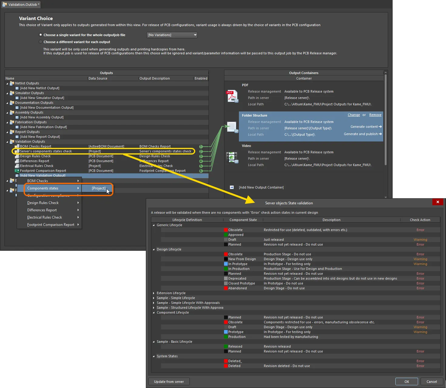
Altium Designer, in conjunction with your connected Workspace, provides an elegant solution to this, in the form of Component State Checking. A validation-based outputter is available for addition to an Output Job file – Components states. This can be configured to check for components that are in restricted states. As part of configuration, you determine the action to be taken for each currently defined state, of each currently defined Lifecycle Definition in the Workspace – no action, a warning, or generate an error. The latter will prevent release of the design. In addition, running the check will generate a handy HTML-based report, allowing you to see at-a-glance which design components are not in valid states.
Issues with using design items in restricted states can also be detected much earlier in the design cycle, during project validation. This concerns an Item Revision's applicability based on its current state, and whether it is allowed to be used in designs while in that state. This is controlled through use of a dedicated attribute at the individual state level. A project violation can be configured to detect and flag any Workspace items being used in a design, whose revisions are in non-applicable states – catching and averting issues prior to release. For more detail, see the
Controlling Item Revision Visibility and Applicability section of the
Defining Lifecycle Definitions for a Workspace page.
When enforcing the working environments of your designers through the use of
Environment Configurations, you can ensure the use of the Output Job file in which component state checking has been defined. To do so, make sure the Output Job file permitted for use through the applicable environment configuration is marked as required – by enabling its
Req'd attribute. If an OutJob defined as part of an environment configuration is marked as required, then release will not be possible until that OutJob is present and enabled for inclusion in the relevant data set being generated as part of project release. For more information, see
Managing Environment Configurations.
Add an output generator of this type from the Validation Outputs section of the OutJob file. Configuration is performed in the Server objects State validation dialog.
To access this configuration dialog, either double-click on the entry for the outputter, right-click on its entry and choose Configure from the context menu, or select its entry and use the Alt+Enter keyboard shortcut.

Add and configure a component state check as part of your overall validation regimen during board design release.
Options and Controls of the Server objects State validation Dialog
The dialog presents all lifecycle definitions defined for the Workspace to which you are actively connected. For each definition, each uniquely defined state is listed, along with its description. For each state associated with a lifecycle definition you employ for components in your designs, simply specify the checking action to be taken. Click within a state's Check Action field and select the required action from the associated drop-down menu. Available checking options are None, Warning, and Error.
Click the

button to refresh the dialog with the latest lifecycle definition information, directly from the Workspace.
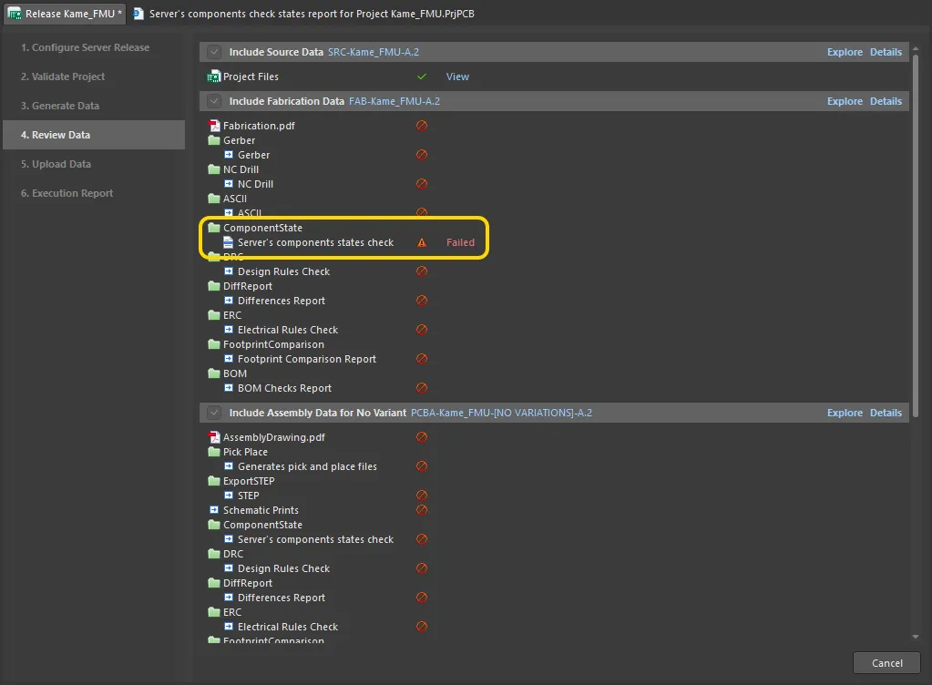
Revisions of Component Items used in the design that are in a restricted state (one whose Check Action has been set to Error) will prevent the release of the board from happening. The generated report file will list all warnings and errors.

Example board release failing at the validation stage while checking component states. Hover over the image to see the generated report. Here, the design is found to contain four components that are in a restricted lifecycle state, and the release process is terminated in failure.
If you are using Workspace output job templates, ensure the component state check is added to the relevant source Output Job file and configured
BEFORE releasing that OutJob to the Workspace. Once released, the revision of the OutJob file – specifically the configuration of an output generator – can not be changed. You would need to make changes and re-release into the next planned revision of the target Item. For more information, see
Preparing Manufacturing Data with Output Jobs.
Preparing an Environment Configuration Compliance Check Report
The Environment Configuration Compliance Check provides a means to conclusively test and enforce the use of company-authorized data elements in a design – i.e. if you are not using data items permitted through the environment configuration available for use by your assigned role, the release will fail. This prevents a 'loose cannon' approach to design and ensures adherence to and compliance with the working design environments determined centrally at the enterprise level.
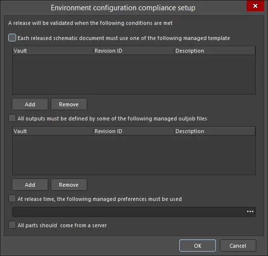
The required report is configured in the Environment Configuration Compliance Setup dialog.

The Environment configuration compliance setup dialog
Options and Controls of the Environment configuration compliance setup Dialog
-
Each released schematic document must use one of the following managed template - check this option to add a managed template(s). This determines which managed schematic templates can be used by source schematic documents in the design.
-
Add - click to open the Choose Item dialog to select the desired template.
-
Remove - click to remove the selected template(s) from the list.
-
All outputs must be defined by some of the following managed outjob files - check this option to add a managed outjob file(s). This determines which managed output job items can be used to generate outputs from the design.
-
Add - click to open the Choose Item dialog to select the desired file(s).
-
Remove - click to remove the selected file(s) from the list.
-
At release time, the following managed preferences must be used - check this option to select the managed preferences that must be used upon release. Use  to select the desired preferences.
-
All parts should come from a server - check this option to ensure that all parts in the design come from a server. If this option is checked and one or more parts are not from a server, the validation will fail.
Learn more about Environment Configuration Management in Altium 365, and in an Enterprise Server Workspace.
Preparing a Differences Report
The Differences Report output generator produces a report that details differences between the project's source schematic and PCB documents.
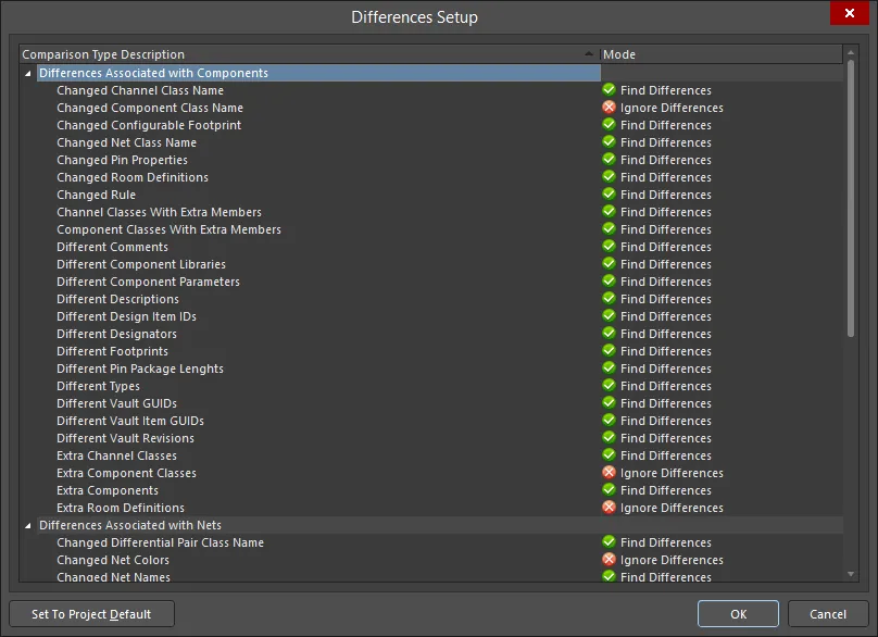
The required report is configured in the Differences Setup dialog.

The Differences Setup dialog
Options and Controls of the Differences Setup Dialog
-
Comparison Type Description/Mode - this is a list of all differences that are available to be checked and reported. Click the entry in the Mode column to choose from the following comparison types:
-
Ignore Differences
-
Find Differences
-
Set To Project Default - click to revert to the default settings.
Learn more about Keeping the Schematics and PCB Synchronized.
Preparing an Electrical Rules Check Report
The Electrical Rules Check output generator produces a report that details violations of drafting and electrical checks for the project's source schematic documents.
The required report is configured in the Electrical Rules Check Setup dialog.

The Electrical Rules Check Setup dialog
Options and Controls of the Electrical Rules Check Setup Dialog
The chosen settings can be stricter or more lenient than the settings defined in the Project Options for your project. You can reset the settings of your Electrical Rules Check to the same as your Project Options by clicking the Set To Project Default button.
Columns Tab
-
Validation - use the drop-down to define the maximum tolerated error level when using the ERC output generator as part of validation during the board design release process. The validation stage of the release process flow (in either Design or Release modes) uses the checking defined in the Output Job only and not the project-level ERC checking. In this way, you can define an even more restrictive/rigid set of checks to be passed, in turn ensuring even higher integrity of the design data. Options include:
 ,
,  ,
,  .
.
-
Suppressed Errors - enable this option to report any suppressed errors.
-
Show Columns - choose which columns are to be displayed in ERC report. Options include Class, Document, and Message. As selections are made, the Preview region is updated to show column settings.
-
Preview - shows the current errors detected for the design, based on validation using the error checking defined on the tabs within the dialog. Change a checking level and the design is re-validated (recompiled) dynamically, and the preview region is updated. Use the options in the Show Columns region to toggle display of the corresponding columns within the preview area.
Error Reporting Tab
This tab enables you to define the reporting levels for each of the possible violations that can exist on source schematic documents when compiling the project. When the project is compiled, these violation settings will be used in conjunction with the Connection Matrix tab to test the source documents for violations. Any violations that are found that have a report level of No Report, Warning, Error, or Fatal Error will be displayed as violation messages in the Messages panel. In addition, if compiler errors and warnings are enabled for display on the schematic (enabled on the Schematic - Compiler Preferences page of the Preferences dialog), an offending object will display a colored squiggle beneath it.
Violations Grid
This region presents all possible violations that can exist on the source documents of the project. Violations themselves are gathered into the following categories:
Each specific violation type is presented with the following fields:
-
Violation Type Description - a short description of the type of violation.
-
Report Mode - use this field to specify the severity level associated with violating the check. Use the drop-down to choose from the following reporting levels:
Right-Click Menu
The following commands are available from the right-click menu:
-
All Off - set the Report Mode for all violation types to No Report.
-
All Warning - set the Report Mode for all violation types to Warning.
-
All Error - set the Report Mode for all violation types to Error.
-
All Fatal - set the Report Mode for all violation types to Fatal Error.
-
Default - set the Report Mode for all violation types back to their default settings.
Multiple violation types can be selected using standard multi-select techniques (Ctrl+click, Shift+click).
Notes
-
Use the Connection Matrix tab to specify reporting levels associated with electrical violations concerning pins, ports and sheet entries specifically.
-
There may be points in the design that you know will be flagged as electrical violations that you do not want to be flagged. To suppress these, place a No ERC schematic design directive object at those points.
-
Generally, it is better to first compile the design and examine the warnings with the default settings. For those warnings that are not an issue for the current design, the reporting level can be changed.
Connection Matrix Tab
This tab displays a matrix that provides a mechanism to establish connectivity rules between component pins and net identifiers, such as Ports and Sheet Entries. It defines the logical or electrical conditions that are to be reported as warnings or errors. For example, an output pin connected to another output pin would normally be regarded as an error condition, but two connected passive pins would not.
When the project is compiled, these violation settings will be used in conjunction with the defined settings on the Error Reporting tab to test the source documents for violations. Any violations that are found and have a report level of No Report, Warning, Error, or Fatal Error will be displayed as violation messages in the Messages panel. In addition, if compiler errors and warnings are enabled for display on the schematic (enabled on the Schematic - Compiler page of the Preferences dialog), an offending object will display a colored squiggle beneath it.
Matrix
The matrix presents all possible wiring connection checks, between combinations of pins, ports, and sheet entries, as well as testing for unconnected entities. The matrix is read in an across/down fashion and the color of the matrix element at the row-column intersection specifies how the compiler will respond when testing for that particular condition.
To change the reporting mode for a violation check in the matrix, simply click on the colored square where the row and column of two entities intersect. Each time you click, the mode will move to the next report level. The following levels are supported:
As you hover over a square, text is displayed below the matrix to describe the violation and the reporting mode.
Right-Click Menu
The following commands are available from the right-click menu:
-
All Off - set all entries in the matrix to No Report.
-
All Warning - set all entries in the matrix to Warning.
-
All Error - set all entries in the matrix to Error.
-
All Fatal - set all entries in the matrix to Fatal Error.
-
Default - set all entries in the matrix back to their default settings.
Notes
-
Use the Error Reporting tab to specify reporting levels associated with further electrical and drafting violations.
-
There may be points in the design that you know will be flagged as electrical violations that you do not want to be flagged. To suppress these, place a No ERC schematic design directive object at those points.
Additional Control
Learn more about Validating your Design Project.